Carbon brake disc negative pressure directional flow outward thermal gradient chemical gas phase penetration process and apparatus

A carbon brake disc, directional flow technology, applied in mechanical equipment, gaseous chemical plating, coating and other directions, can solve the problems of affecting the uniformity of density, low carbon deposition efficiency, easy crusting on the surface, etc., to reduce equipment power consumption, widening the dense belt of deposited carbon, and good friction characteristics

Active Publication Date: 2004-11-10
XIAN CHAOMA SCI TECH
View PDF0 Cites 14 Cited by
  • Summary
  • Abstract
  • Description
  • Claims
  • Application Information

AI Technical Summary

Problems solved by technology

British Dunlop Company, French Carbon Industie Company, American Goodyear, Bendix Company, etc. all use the soaking CVI process to manufacture carbon brake disc materials. This traditional process has the characteristics of adapting to industrial scale production and products are not limited by geometric shapes, but there is carbon deposition. Low efficiency, long production cycle, easy crusting on the surface, multiple intermediate graphitization openings or machining, etc.
B.F.Goodrich Company of the United States and my country's 514 factory use differential pressure CVI technology to manufacture aircraft carbon brake disc materials. Although the production cycle can be shortened, it is only used when the density of carbon brake discs is low. When the density increases, the air permeability of the product changes. Poor, stil

Method used


Image

  • Carbon brake disc negative pressure directional flow outward thermal gradient chemical gas phase penetration process and apparatus

Examples


Embodiment Construction

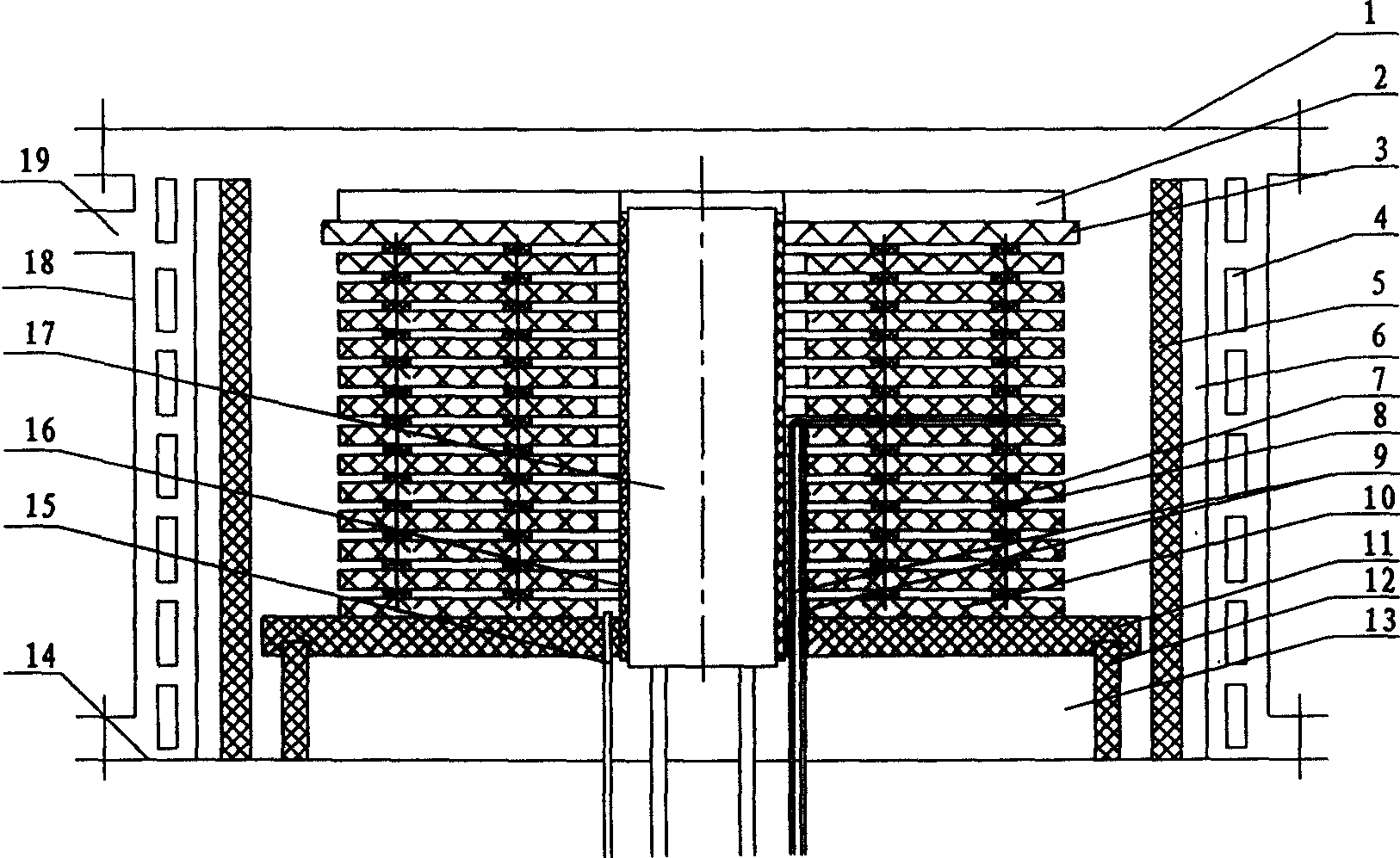
[0024] Such as figure 1 As shown, the directional flow external thermal gradient CVI equipment designed by the present invention consists of a furnace cover 1, a graphite cover plate 3 and an insulating felt 2 on it, a graphite heating element 5 and an insulating felt 6 located outside it, and a Copper induction coil 4, carbon plate prefabricated body 7, graphite gasket 8, thermocouple 9, insulation layer 10, graphite pallet 11, graphite bracket 12, insulation felt 13, furnace bottom 14, air intake pipe 15, insulation felt 16, The inner water cooling device 17, the outer furnace body 18, and the air extraction hole 19 are formed. The inner water cooling device 17 is arranged on the bottom of the furnace 14, and is inserted into the inner diameter of the charcoal disc prefabricated body 7, and is provided with a certain distance from the charcoal disc prefabricated body 7. The water cooling device 17 is a water pipe for internal cooling water, and the temperature difference bet...


PUM


Abstract

The invention is an airplane carbon brake disc's negative pressure orientation flow external thermal gradient chemical gas-phase osmosis method, its character: placing the prefabricated bodies of airplane carbon brake disc in a furnace, inserting equal-thickness graphite slices between the prefabricated bodies; under negative pressure, making the prefabricated bodies internally hot and externally cold, establishing thermal gradient in the radial direction; under negative pressure, carbon source gas directionally flows through the equidistant slots between the prefabricated bodies almost at 100%; adopting the temperature difference of 0.3 deg.C/cm-25deg.C/cm or the internal and external total temperature difference of 30 deg.C -380 deg.C; making carbon source gas enter the inside of prefabricated bodies, directionally flow through the equidistant slots, and discharged out of the furnace from the outer side; the compacting course of the prefabricated bodies gradually goes from outside high-temperature surface to inside low-temperature surface, an by gas-phase carbon deposition, preparing the finished products. It can effectively enhance carbon utilization ratio and has good friction character and high thermal efficiency, applied to various types of structures of airplane carbon brake discs and tail discs, shortens production period, reduces cost and applies to industrial scaled production.

Description

Technical field [0001] The invention relates to a method and equipment for manufacturing aircraft carbon brake discs, in particular to a method and equipment for manufacturing aircraft carbon brake discs by adopting negative pressure directional flow outer heat and inner cold heat gradient chemical vapor infiltration (CVI) technology. Background technique [0002] The CVI process is a well-known method for manufacturing high-temperature structural carbon / carbon composite materials from dense carbon fiber preforms, such as aircraft carbon brake discs, solid rocket engine nozzle carbon / carbon throat linings, expansion sections and other materials. . The traditional CVI process is divided into four types: soaking method, thermal gradient method, differential pressure method and pulse method. British Dunlop Company, French Carbon Industie Company, American Goodyear, Bendix Company, etc. all use the soaking CVI process to manufacture carbon brake disc materials. This traditional...

Claims


Application Information

Patent Timeline
IPC IPC(8): C23C16/26F16D69/00
Inventor 苏君明肖志超孟凡才向嵛朱寿庆李睿
Owner XIAN CHAOMA SCI TECH
Why Eureka
Try Eureka