Method and its device for preparing cutter by laser coating composite ceramic layer

A technology of laser coating and composite ceramics, which is applied in the field of ceramic materials and ceramic coatings on metal surfaces, can solve the problems of large tool consumption, high tool cost, and high price, and achieve high production efficiency, improved service life, and coating good quality effect

Inactive Publication Date: 2004-12-15
HUAZHONG UNIV OF SCI & TECH
View PDF0 Cites 24 Cited by
  • Summary
  • Abstract
  • Description
  • Claims
  • Application Information

AI Technical Summary

Problems solved by technology

At present, most domestic manufacturers of short fibers use Romus cutting knives. The Romus cutting knives are made of L135 hard alloy, sintered as a whole, and finally ground to shape. However, the cost of this tool is high and the price is relatively expensive. Shaped hollow knife holder, each payment is 56 pieces, due to the fast wear of the knife edge, the consumption of the knife is large

Method used


Image

  • Method and its device for preparing cutter by laser coating composite ceramic layer
  • Method and its device for preparing cutter by laser coating composite ceramic layer
  • Method and its device for preparing cutter by laser coating composite ceramic layer

Examples


Embodiment 1

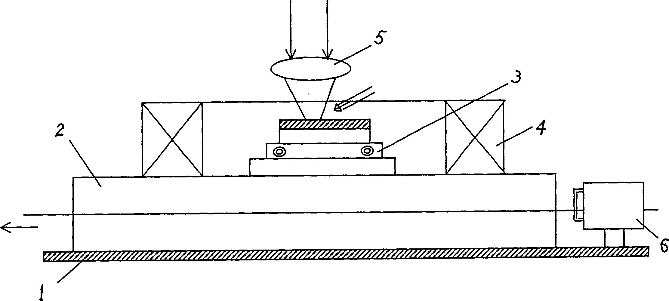
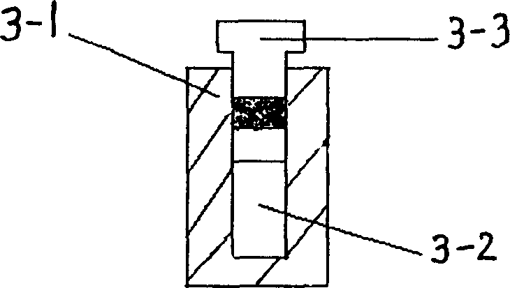
[0026] figure 1 It is a schematic diagram of the chemical fiber cutting knife laser coating device provided by the present invention. On the base 1, a workbench 2 and a special fixture 3 for presetting powder placed on the workbench 2 are installed. Electromagnetic coils 4 are arranged on both sides of the special fixture 3. Above the special fixture 3 is the laser processing system 5, the workbench 2 is driven by the motor 6 to move in the X direction, and the preset powder special fixture 3 is as figure 2 As shown, it is made up of concave groove 3-1, cushion block 3-2 and wedge-shaped briquetting block 3-3.

[0027] Use 2-3kw cross-flow continuous CO 2 Laser, the laser wavelength is 10.6μm, and the beam mode is multimode. Cobalt-based WC alloy powder with more than 200 meshes is selected, and 25% Tic, 8% Tac, 1% Al are added 2 o 3 , 1% SiO 2 , 0.05%Y 2 o 3 and 1% Al powder, etc., and the mixed powder is ball milled by a ball mill to make the powder mix evenly.

[00...

Embodiment 2

[0038] Choose 100-150 mesh cobalt-based tungsten carbide and 20% Tic, 8% Tac, 2% Al 2 o 3 , 0.5% SiO 2 , 0.1%Y 2 o 3 Mixed powder composed of carbide, oxide and 0.5% Al.

[0039] The laser coating composite ceramic coating prepares the cutting tool and adopts the method of laser coating while feeding powder, and its method does not add electromagnetic stirring, and the rest of the process is the same as in Example 1, and its process parameters are:

[0040] Laser beam power: 1.6-1.8kw

[0041] Laser beam spot diameter: 2.0-2.5mm

[0042] Scanning speed: 8-12mm / s

[0043] Shielding gas: Ar

[0044] Laser coating thickness: 0.8-1.0mm

Embodiment 3

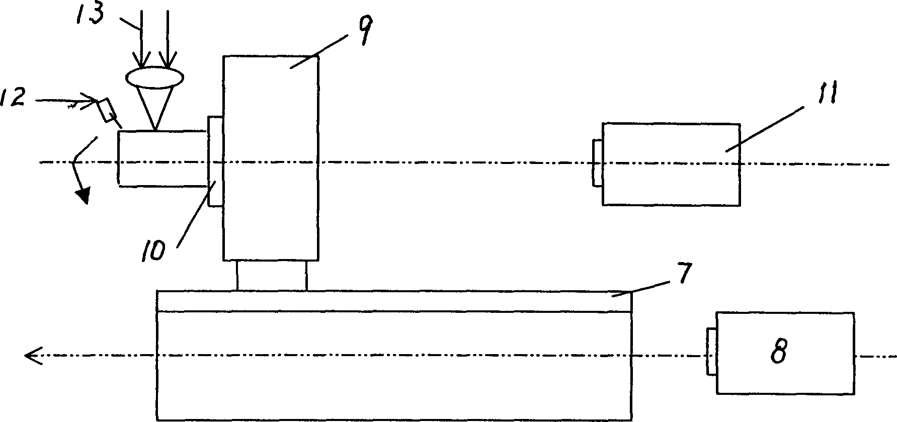
[0046] Laser coated 9CrSi material is used to prepare milling cutter blades. For the specific laser coating device for milling cutter blades, see image 3, which includes a workbench 7, a chuck device placed on the workbench, a chuck motor 11 on one side of the chuck device, an air powder feeder 12 located on the other side of the chuck device, and a laser processing system 13, the chuck The device consists of an indexer 9 and a three-jaw chuck 10. The laser processing system is located above the chuck device and the air powder feeder 12. The workbench 7 is driven by the workbench motor 8 to move in translation in the X direction.

[0047] The laser coating powder uses an inorganic resin (or organic) binder to adjust the mixed powder into a paste, and coats the powder on the helical blade of the milling cutter. See the attached figure. The laser coating process is as follows:

[0048] The laser beam is aimed at the pre-set powder of the milling cutter, and the milling cutter i...


PUM

PropertyMeasurementUnit
hardnessaaaaaaaaaa

Abstract

The present invention relates to method and apparatus for making cutter with laser coated composite ceramic layer, belongs to the field of ceramic coating on metal surface, and aims at lowering cutter manufacturing cost while prolonging the service life of cutter. The cutter making process includes applying hard alloy powder to the surface of cutter base, applying mechanical pressure, preheating, and laser treating after or while applying the hard alloy powder. The cutter made may be chemical fiber cutter, milling cutter or trimming cutter. One of the cutter making apparatus includes bench, special fixture, electromagnetic coil and laser processing system. The other cutter making apparatus includes bench, chuck, powder blowing feeder and laser processing system. The present invention has high coating quality, less heat deformation, high production efficiency and other advantages.

Description

technical field [0001] The invention belongs to the field of ceramic materials, in particular to the field of ceramic coatings on metal surfaces. Background technique [0002] Ceramic materials have been widely used to make cermet knives at present, and the combination of ceramic materials and the knives (knife base) is usually connected by adhesive or by hot pressing or sintering. Chemical fiber cutting knives are cutting knives in the production of man-made fibers and synthetic fibers. The quality and cost of chemical fiber cutting directly affect the production efficiency of short fibers. At present, most domestic manufacturers of short fibers use Romus cutting knives. The Romus cutting knives are made of L135 hard alloy, sintered as a whole, and finally ground to shape. However, the cost of this tool is high and the price is relatively expensive. On the shaped hollow tool holder, each pay 56, because the tool blade wears fast, the tool consumption is large. Contents o...

Claims


Application Information

Patent Timeline
Patent Type & Authority Applications(China)
IPC IPC(8): B23K26/34C23C24/10
Inventor 郑启光余莲卿陶星之童杏林
Owner HUAZHONG UNIV OF SCI & TECH
Why Eureka
Try Eureka