Photoelectrocatalysis and oxidation device for treating organic substance in water

A photoelectric catalysis and oxidation treatment technology, applied in the direction of oxidized water/sewage treatment, electrochemical water/sewage treatment, light water/sewage treatment, etc., can solve the problems of mass transfer, reaction rate needs to be improved, etc., to achieve treatment efficiency High, compact and reasonable effect

Inactive Publication Date: 2005-01-12
TAIYUAN UNIV OF TECH
View PDF0 Cites 43 Cited by
  • Summary
  • Abstract
  • Description
  • Claims
  • Application Information

AI Technical Summary

Problems solved by technology

In recent years, someone has introduced the air oxygen electrode cathode into the electrophotochemical system (Cai Naicai, Wang Yaping, Wang Efeng, etc. Applied Chemistry, 1999, 16 (2): 87-89; Tomas Harr...

Method used


Image

  • Photoelectrocatalysis and oxidation device for treating organic substance in water
  • Photoelectrocatalysis and oxidation device for treating organic substance in water
  • Photoelectrocatalysis and oxidation device for treating organic substance in water

Examples


Embodiment approach 1

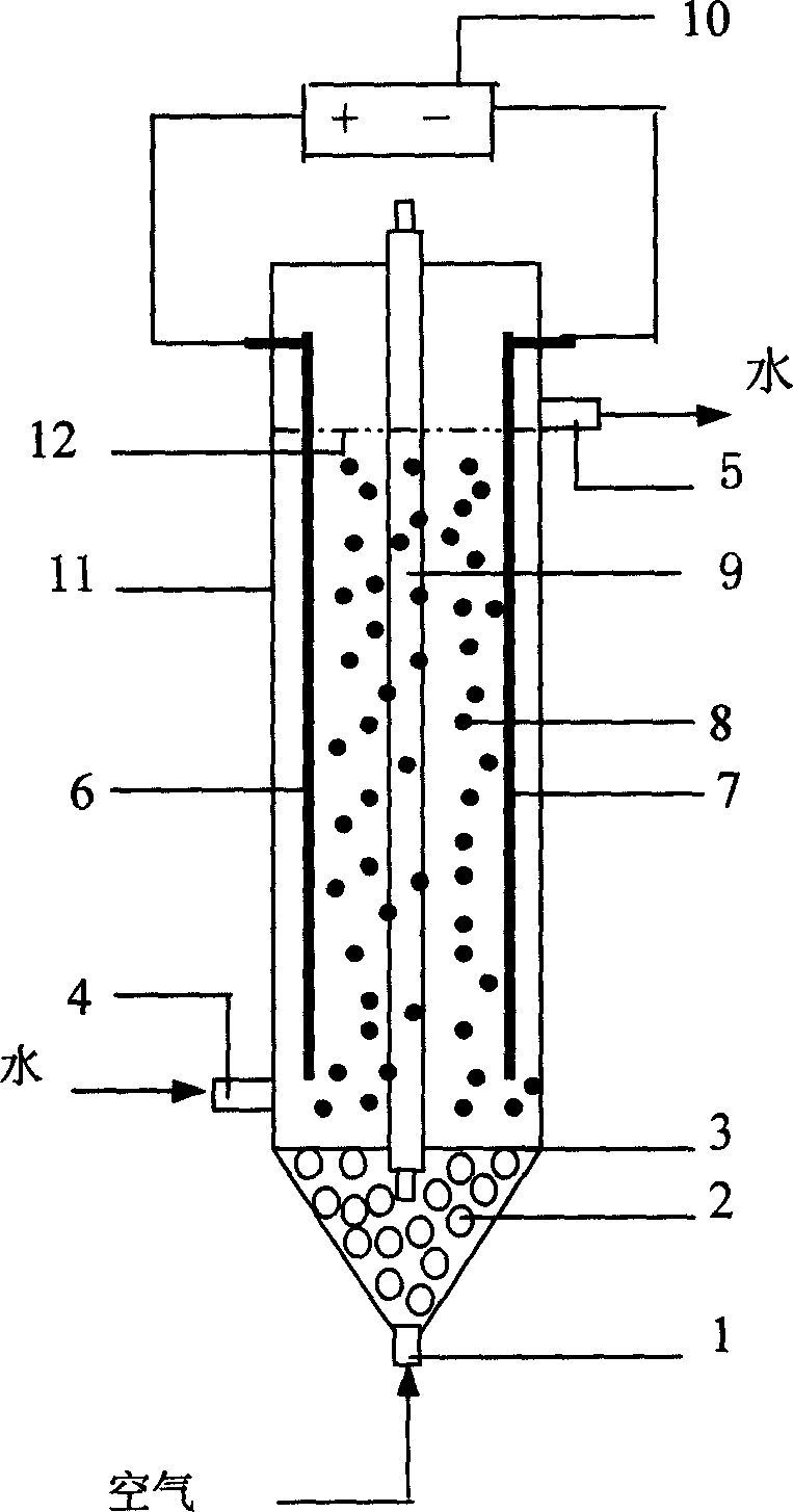
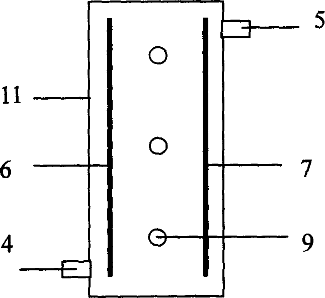
[0025] refer to figure 1 , the reaction device structure of the fluidized bed photocatalytic oxidation treatment of organic matter in water of the present invention is as follows: titanium-based oxide TiO 2 / SnO 2 The / Ti anode 6 is the anode, the air oxygen electrode cathode 7 is the cathode, and the cathode and the anode are respectively provided with electrical connectors that can be connected to a DC power supply 10; compressed air is used as the gas source; the particles are coated with commercial activated carbon and graphite powder TiO 2 Formed TiO 2 The / C fluidized particles 8 are photocatalyst particles. Compressed air enters the bottom air chamber of the reactor from the air inlet 1, and blows air into the reactor through the microporous air distribution plate 3. The two electrodes stand opposite each other, each close to a wall of the device. TiO 2 / C Fluidized particles are placed on the air distribution plate and are in a fluidized state under the action of...

Embodiment approach 2

[0028] According to the device structure and treatment process of Embodiment 1, the water-soluble humic acid solution is treated. The setting conditions are: 15W UV light source, TiO 2 / C photocatalytic fluidized particle size 1.5mm, P25 TiO 2 The concentration is 1.5g / L, and the air flow rate is 0.5m 3 / h, TiO 2 / SnO 2 / Ti is the anode, the air oxygen electrode is the cathode, the distance between the negative and positive electrodes is 8cm, and the electrode area is 20cm 2 , current density 15mA / cm 2 . After 1 hour of photoelectric catalytic reaction, the COD removal rate of 20mg / L, 120mL water-soluble humic acid solution was 86.2%, and the decolorization rate was 100%.

Embodiment approach 3

[0030] According to the device structure and treatment process of Embodiment 1, the formic acid aqueous solution is treated. The setting conditions are: 15W UV light source, TiO 2 / C photocatalytic fluidized particle size 2mm, P25 TiO 2 The concentration is 0.8g / L, and the air flow rate is 0.6m 3 / h, TiO 2 / SnO 2 / Ti is the anode, the air oxygen electrode is the cathode, the distance between the negative and positive electrodes is 15cm, and the electrode area is 20cm 2 , current density 15mA / cm 2 . After 1 hour of photoelectric catalytic reaction, the COD removal rate of 460mg / L and 120mL formic acid aqueous solution was 96.8%, and the decolorization rate was 100%.


PUM


Abstract

Fluid-bed photo-electro catalytic organic water processing device consists of titanium-base oxide positive electrode, negative oxygen electrode, TiO2/C sulfide particle, ultraviolet light source, constant potentiometer DC power source, air distribution board and casing. Not only oxidizing action of positive electrode and reducting action of negative oxygen electrode are used, but also active perssad OH, H2O2, OH- and light, photocatalysis are used, to go deep into bed layer by strong stirring of fluidized particle to increase OH density of the system and to be uniform, TiO2 on surface of fluidized particle produces OH by lighting continuously, and surface of TiO2 particle is renewed continuously.

Description

technical field [0001] The invention relates to a photocatalytic oxidation treatment device for organic matter in water, which belongs to the technical field of environmental chemical industry photocatalytic oxidation water treatment. Specifically, a fluidized bed photocatalytic organic water treatment device is disclosed. technical background [0002] Since the middle of the 20th century, with the rapid development of industry, a large number of non-living organic matter that did not exist in nature has been produced, most of which are refractory organic matter, posing a great threat to the ecological environment and human survival. [0003] Photoactive semiconductors (usually TiO 2 ) on the valence band (Fujishima A, Honda K, Nature, 1972, 238: 37-38; Matthews R.W.J. Catal.1988, 111: 264-272; Ollis D F, Al-Ekabi H. Amsterdam: Elsevier, 1993 ), produce OH free radicals with strong oxidizing ability in water (standard electrode potential 2.80eV), which can completely miner...

Claims


Application Information

Patent Timeline
IPC IPC(8): B01J21/00C02F1/32C02F1/46C02F1/72
Inventor 樊彩梅孙彦平
Owner TAIYUAN UNIV OF TECH
Why Eureka
Try Eureka