
Matrix type biochip CCD scanning fetch device

A biochip and reading device technology, applied in the field of CCD scanning and reading devices, can solve the problems of high background noise, high cost of replacing a new light source, low photoelectric conversion efficiency, etc., and achieve the effect of reducing background noise and simplifying the structure of the optical path system

Inactive Publication Date: 2005-02-16
BEIHANG UNIV
View PDF0 Cites 16 Cited by
  • Summary
  • Abstract
  • Description
  • Claims
  • Application Information

AI Technical Summary

Problems solved by technology

[0004] The structure of the confocal optical path adopted by the above-mentioned scanning and reading instrument is complicated, and the suppression of non-focal plane stray light by the confocal optical path does not improve the signal-to-noise ratio, but instead causes the system to be very sensitive to the surface unevenness of the matrix biochip; the laser light source Large size, high cost of replacing a new light source; the angle between the excitation light path and the detection light path is 0°, resulting in high background noise; PMT (photomultiplier tube) photoelectric conversion efficiency is low (<50%); The photodrifting phenomenon of the chip affects the repeated detection of the matrix biochip

Method used


Image

  • Matrix type biochip CCD scanning fetch device
  • Matrix type biochip CCD scanning fetch device
  • Matrix type biochip CCD scanning fetch device

Examples


Embodiment Construction

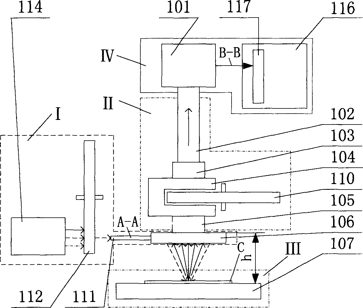
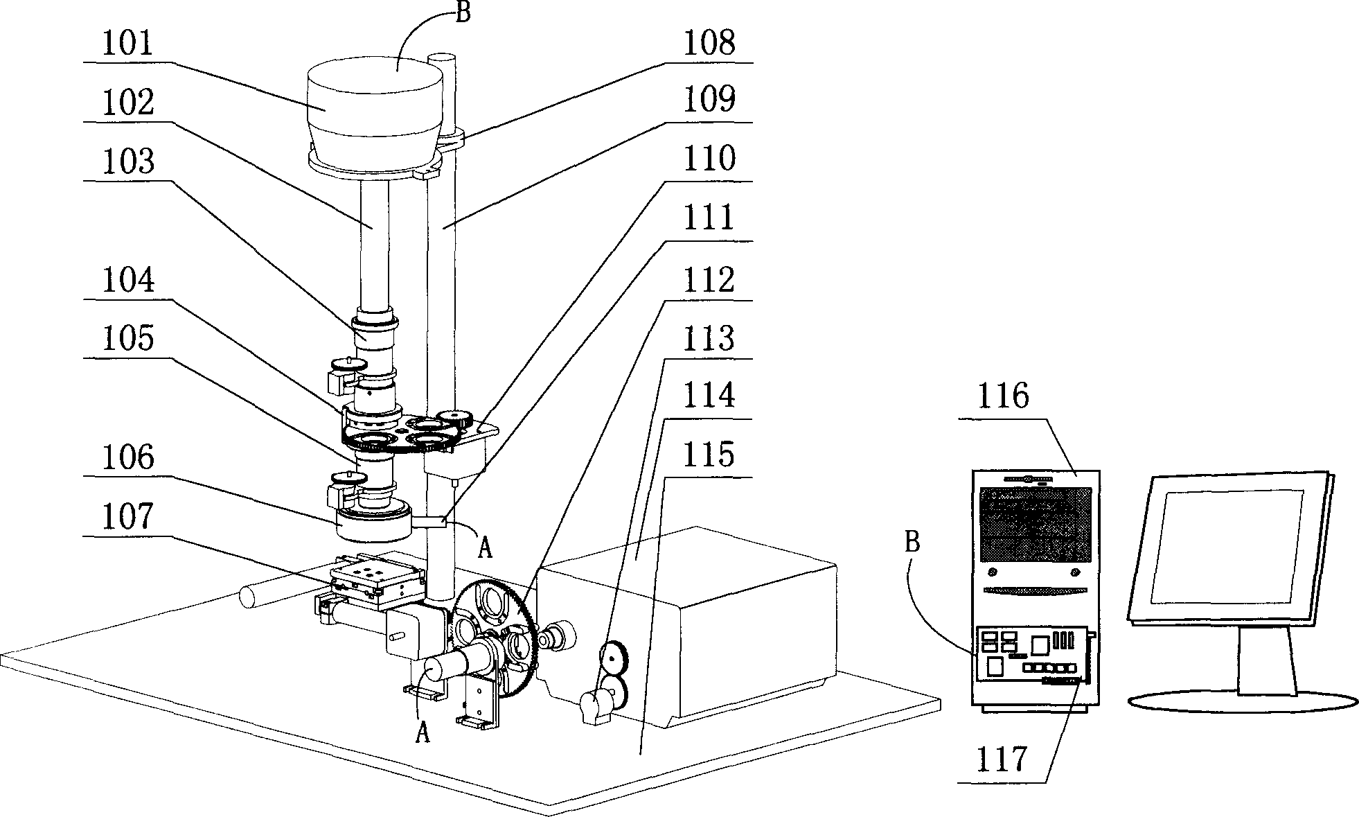
[0018] Such as figure 1 As shown, the embodiment of the present invention includes 4 subsystems. The excitation photosubsystem I produces a uniform excitation light irradiation field suitable for specific bands of different fluorescent dyes; After excitation, the fluorescent images belonging to different fluorescent dyes are emitted; the X-Y scanning platform subsystem III carries and drives the matrix biochip to coordinate the movement to complete the scanning action; the detection subsystem IV releases the fluorescence intensity images collected by the fluorescent subsystem II The acquisition is converted into an electrical signal and saved.

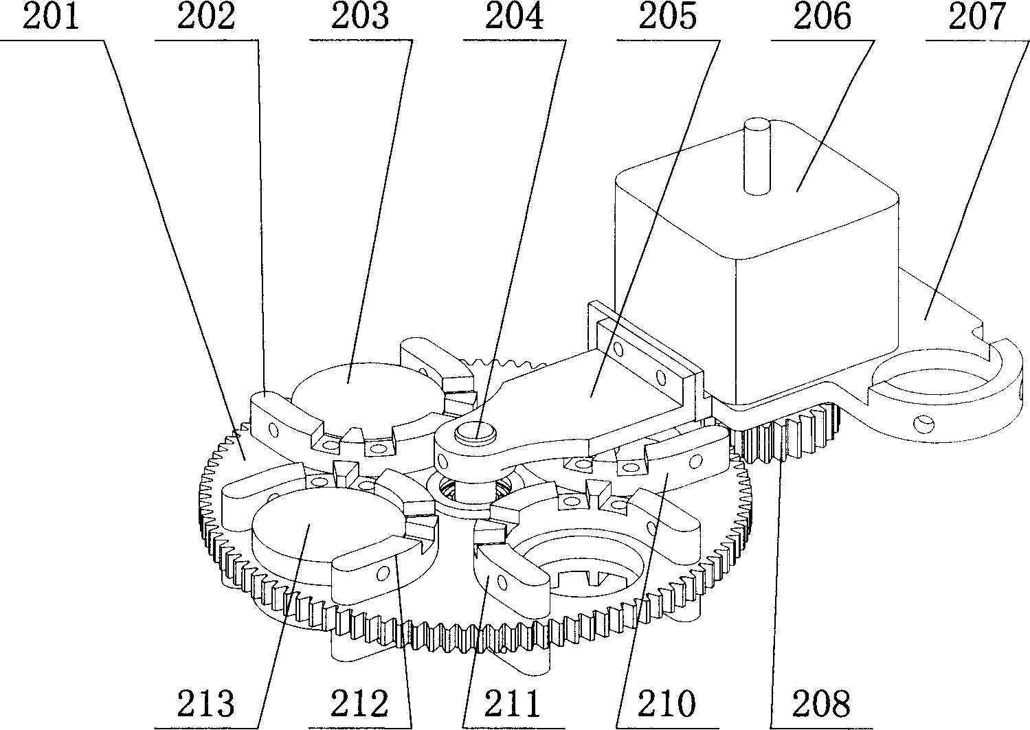
[0019] Such as figure 1 , figure 2 As shown, the above-mentioned excitation photosubsystem I includes: a non-laser light source 114, which adopts a 150W metal halide light source to generate parallel excitation light from 300nm to 700nm in multiple spectral segments; an excitation filter filter wheel 112, which is used to install 2 ...


PUM

PropertyMeasurementUnit
Center wavelengthaaaaaaaaaa
Bandwidthaaaaaaaaaa
Outer diameteraaaaaaaaaa

Abstract

This is a matrix pattern biological chip scanning reading device. It comprises stimulating-photon system, the releasing fluorescence collective subsystem, the X-Y scanning terrace sup system and the testing sub system. The stimulating photon system produce the single color even stimulated light shining field. The matrix pattern biological chip be carried on X-Y scanning terrace sub system, and be placed in the single color even stimulated light shining field, and be driven by the X-Y scanning terrace sub-system to finish whole scanning reading course. The releasing fluorescence collective sub system collect and separate after stimulated matrix pattern biological chip transmitted fluorescence picture, then exchange this picture into electrical signal and store, display it. This invention outstanding features is to use the infinitive non-copolymerizated focusing light pass way to simplify the structure. The CCD is photo-electrical exchanger can raise the exchange efficiency 50-60% and as between the stimulated light way and testing light way is 30 degree angle, reduce the noise of background. This invents suits with the sample's diameter 75-500mu meter matrix pattern biological chip.

Description

technical field [0001] The invention relates to a CCD scanning reading device for detecting the hybridization reaction result of a matrix biochip (Microarray). Background technique [0002] Matrix biochip (Microarray) can be widely used in drug screening and new drug development, disease diagnosis, environmental protection and so on. After hybridization reaction between the samples to be tested labeled with fluorescent dyes (commonly used fluorescent dyes: Cy3, Cy5, etc.) The emitted fluorescence is finally detected by the photoelectric conversion device to detect the intensity of the emitted fluorescence, and then interpret the corresponding biological information. [0003] At present, matrix biochip scanning and reading instruments usually use laser as the excitation light source to generate a monochromatic beam to excite and irradiate matrix biochips. The confocal optical system collects the fluorescence emitted by the chip, and PMT is collected by the photoelectric conv...

Claims


Application Information

Patent Timeline
IPC IPC(8): G01J3/443G01N21/64G01N33/50G01N33/68
Inventor 宗光华毕树生周强李大寨于靖军
Owner BEIHANG UNIV
Learn More