Plasma coal gasifying process and device

A plasma and coal gasification technology, which is used in the petroleum industry, the manufacture of combustible gas, and the mitigation of combined combustion, etc., can solve the problems of short continuous operation time, coking on the inner wall of the reactor, and low gasification load, etc. The effect of solving the coking problem and improving the thermal efficiency

Inactive Publication Date: 2005-08-03
TAIYUAN UNIV OF TECH
View PDF0 Cites 14 Cited by
  • Summary
  • Abstract
  • Description
  • Claims
  • Application Information

AI Technical Summary

Problems solved by technology

[0005] On the basis of the above-mentioned existing plasma coal gasification process and device, the present invention proposes a plasma coal gasification process and device to solve the problems of the existing plasma coal gasification process and device, such as the problem of coking on the inner wall of the reactor, due to coking The problem of short continuous operation time, the problem o

Method used


Image

  • Plasma coal gasifying process and device
  • Plasma coal gasifying process and device
  • Plasma coal gasifying process and device

Examples


Embodiment 1

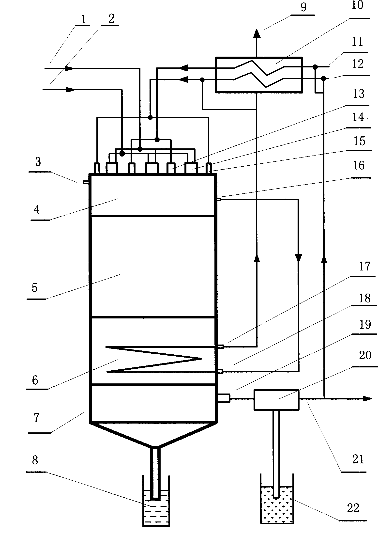
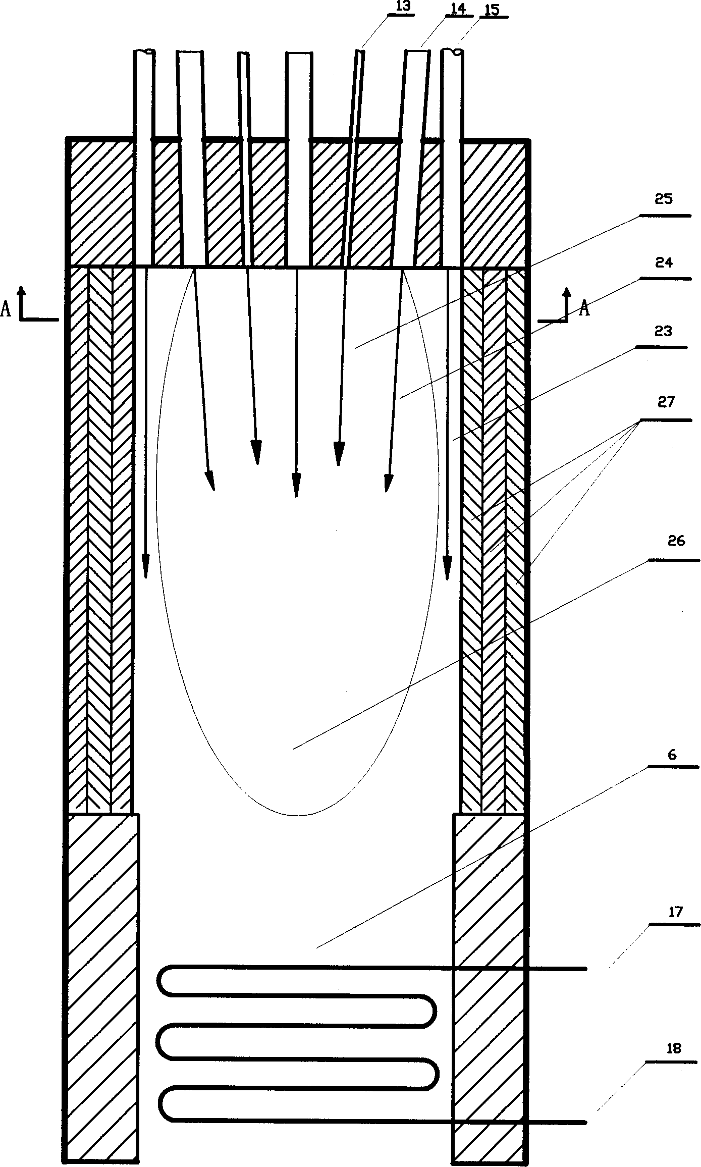
[0022] The present invention has been improved on the basis of original technique and equipment, as attached figure 1As shown, after the working gas (oxygen) is introduced into the plasma generator (4) by the working gas (2) inlet and applied to the power supply (1), a plasma arc (24) is generated in the plasma reactor (5), After the synthesis gas pipe (12) and pulverized coal flow pipe (11) absorb heat through the preheating heat exchanger (10), they are sprayed into the plasma reactor by the synthesis gas steam nozzle (15) and the pulverized coal flow nozzle (13) In (5), the reaction takes place in the plasma reactor (5), and the product passes through the water-steam heat exchanger (6) and enters the gas-solid separator (7) for gas-solid separation, and the separated coal ash enters the closed into the coal ash tank (8), and lift the coal ash to the pulverized coal supply end for recycling, the separated fly ash is used as cement filler, and the separated mixed gas enters t...

Embodiment 2

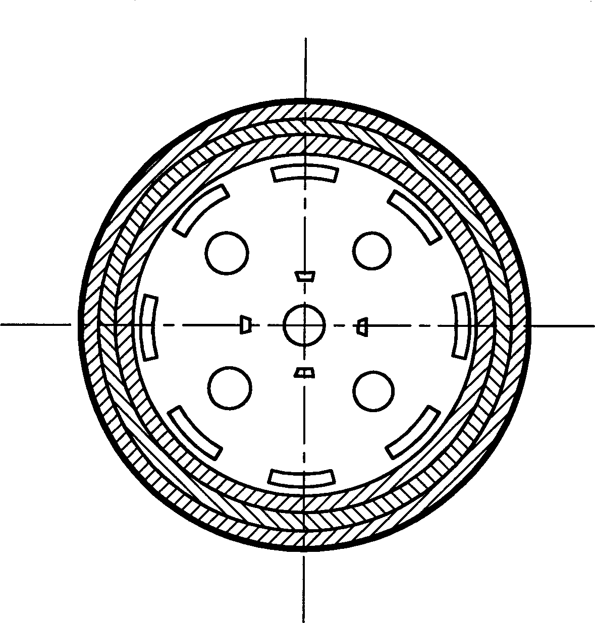
[0028] Devices for plasma coal gasification process, including power supply (1) working gas (2) cooling water jacket inlet (3) plasma generator (4) plasma reactor (5) water vapor heat exchanger (6) gas-solid separator ( 7) Coal ash tank (8) Water vapor outlet pipe of preheating heat exchanger (9) Preheating heat exchanger (10) Pulverized coal airflow pipe (11) Synthetic gas pipe (12) Pulverized coal airflow nozzle (13) Plasma generation Inlet of water vaporizer (14) Syngas steam nozzle (15) Outlet of circulating cooling water jacket (16) Outlet of steam heat exchanger (17) Inlet of water vapor heat exchanger (18) Outlet of gas-solid separator (19) Bag filter ( 20) Syngas output pipe (21) Fly ash tank (22) Syngas barrier (23) Plasma arc (24) Coal powder flow (25) Thermal plasma field (26) Plasma reactor shell (27) Plasma generator shell (28) Plasma anode insulator (29) Plasma anode rod (30) Plasma cathode rod (31) Top cover (32) Working gas channel shell (33) Plasma cathode rod...


PUM


Abstract

The present invention discloses a coal gasifying plasma process and apparatus. After work gas is sprayed into plasma generator and the power supply is applied to produce plasma field, synthetic gas and preheated coal powder are sprayed into the plasma generator for reaction to generate mixed gas; the mixed gas is made to pass through water-gas heat exchanger and enter the gas-solid separator to separate coal ash falling into coal ash tank and synthetic gas entering the bag-type dust collector for further separation; of the separated synthetic gas, great amount is output as the product while part is fed to coal powder pipe and synthetic gas pipe; and plasma generator electrode cooling water is fed to the preheater before being synthesized into steam sprayed to inner wall of the plasma generator to avoid coking. The present invention has reasonable technological process, compact structure, no environmental pollution, long continuous running time, high coal gasifying rate and high efficiency.

Description

technical field [0001] The invention relates to a coal gasification process and equipment, in particular to a plasma coal gasification process and device. Background technique [0002] Coal gasification is one of the key technologies of coal chemical industry. The existing coal gasification process can be divided into three categories: fixed bed, fluidized bed and entrained bed. Lurgi technology is a typical representative of fixed-bed coal gasification technology, which has high requirements on coal quality and can only use lump coal as raw material; high-temperature Wenkler technology is a representative of fluidized bed technology, and this kind of technology has the problem of "vomiting up and down". problems, resulting in low conversion rate; the entrained bed process can be divided into dry feed and wet feed, Shell is the entrained bed technology of dry feed, Texaco and Dow are the entrained bed technology of wet feed, However, it is required to match the ash melting...

Claims


Application Information

Patent Timeline
IPC IPC(8): C10J3/00
CPCY02E20/18
Inventor 杨巨生谢克昌张永发鲍卫仁吕永康
Owner TAIYUAN UNIV OF TECH
Why Eureka
Try Eureka