Composite scanning chlorion sensitive micro-probe and preparing process thereof
A micro-probe, chloride ion technology, applied in the field of probes, can solve the problems of slow response speed, short service life of liquid membrane electrodes, and difficult fabrication of micro-electrodes, etc., and achieves small tip size, simple preparation process, and improved spatial resolution. effect of ability
- Summary
- Abstract
- Description
- Claims
- Application Information
AI Technical Summary
Problems solved by technology
Method used
Image
Examples
Embodiment 1
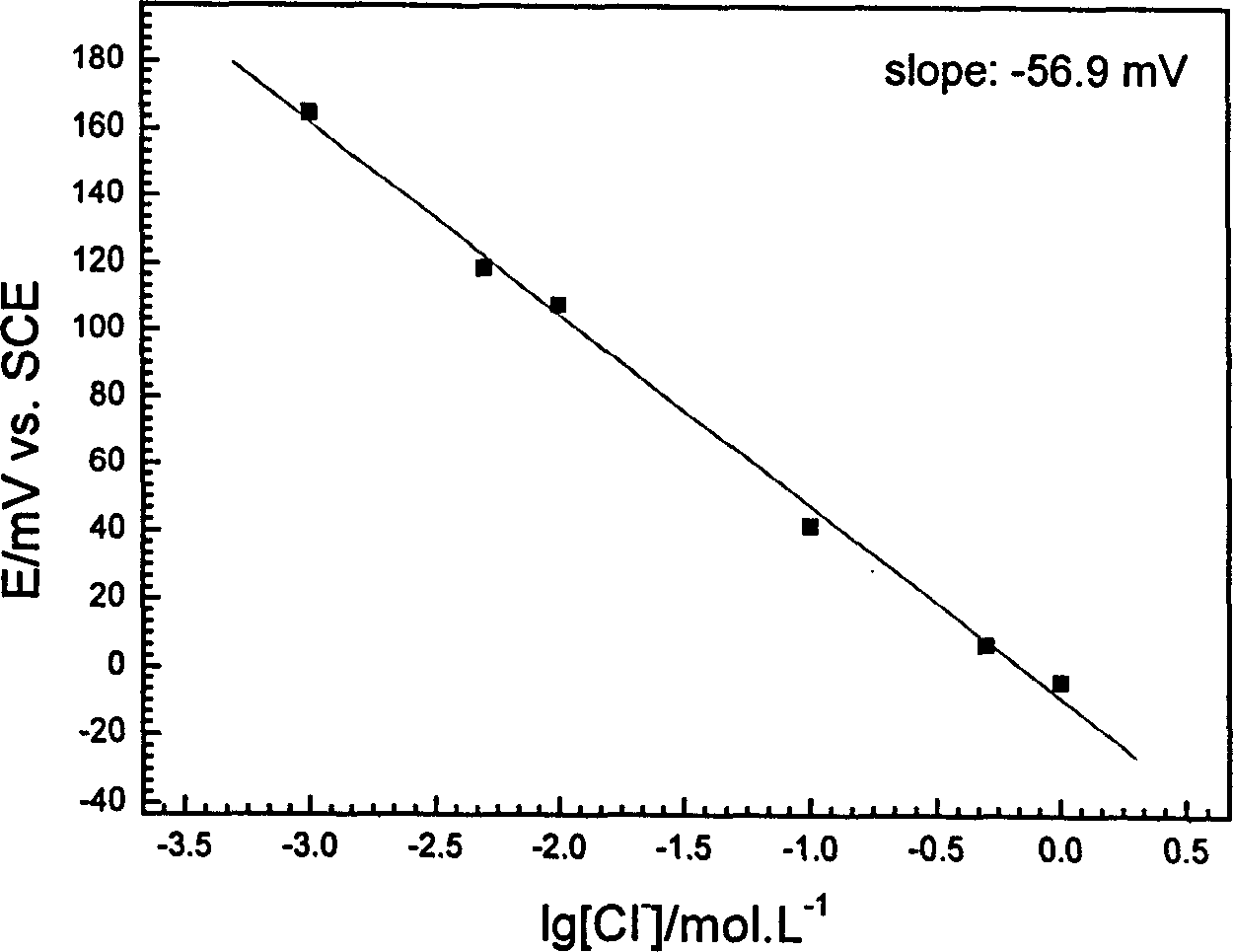
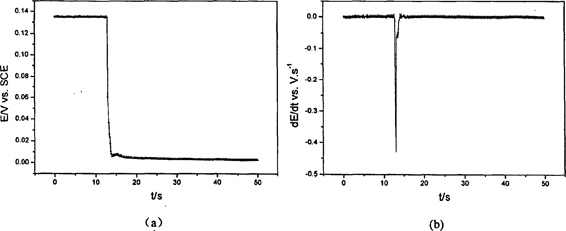
[0025] The drugs used are all analytically pure, and the preparation solution uses three times of deionized water. The measurement of Ag / AgCl electrode potential-concentration curve and potential-time curve is completed by the Autolab electrochemical workstation of Eco Chemi Company. The 18-8 stainless steel is polished with 400 to 1000 water abrasive paper in turn, polished with 1 μm alumina polishing powder to a mirror surface, ultrasonically cleaned with anhydrous ethanol and water three times, and dried. The micro-area scanning measurement of the chloride ion concentration on the metal surface was completed by the scanning electrochemistry / scanning tunneling microscope system developed by Xiamen University.
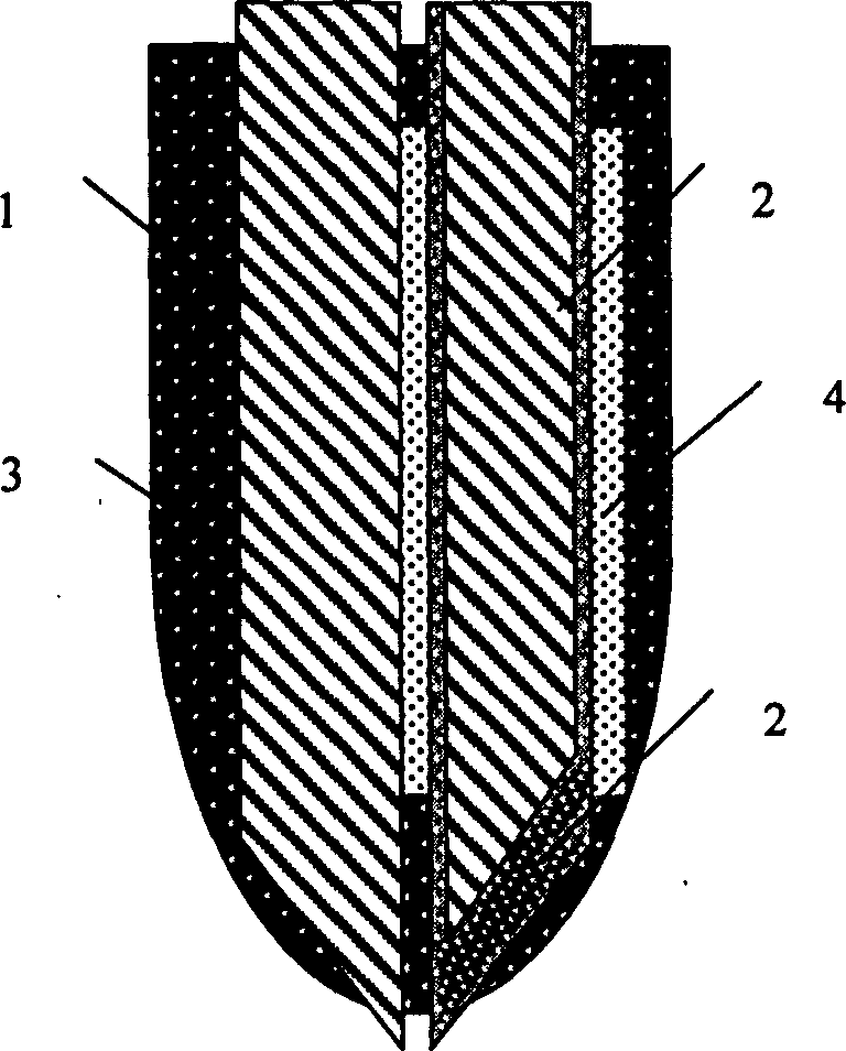
[0026] First, take a pure silver wire with a length of 20mm and a diameter of 0.2mm, mechanically cut out a tip of 50μm at one end with sharp scissors, and then perform a constant current anodizing treatment in a HCl solution with a concentration of 0.01mol / L for 3h, ...
Embodiment 2
[0031] Similar to Example 1, the difference is that when preparing the Ag / AgCl electrode, a pure silver wire with a length of 50 mm and a diameter of 0.3 mm was used to mechanically cut out a tip of 70 μm at one end with sharp scissors, and then in a concentration of 0.001mol / L Constant current anodizing treatment in HCl solution for 5h, the control current is 0.001mA / cm2. After the anodization is completed, a layer of tan and dense AgCl film is uniformly formed on the surface of the silver wire. After the Ag / AgCl electrode was rinsed with distilled water and dried, the surface was evenly coated with a layer of nail polish with a thickness of 1 μm. When preparing the reference probe, a 50 μm tip was processed at one end of a Pt-Ir alloy (Pt70%-Ir30%) wire with a length of 50 mm and a diameter of 0.3 mm.
Embodiment 3
[0033] Similar to Example 1, the difference is that when preparing the Ag / AgCl electrode, a pure silver wire with a length of 70 mm and a diameter of 0.1 mm was used to mechanically cut out a 20 μm tip at one end with sharp scissors, and then in a concentration of 0.05 mol / L Constant current anodizing treatment in HCl solution for 10h, the control current is 0.01mA / cm2. After the anodization is completed, a layer of tan and dense AgCl film is uniformly formed on the surface of the silver wire. After the Ag / AgCl electrode was rinsed with distilled water and dried, the surface was uniformly coated with a layer of nail polish with a thickness of 7 μm. When preparing the reference probe, a 20 μm tip was processed at one end of a Pt-Ir alloy (Pt70%-Ir30%) wire with a length of 70 mm and a diameter of 0.5 mm.
PUM
| Property | Measurement | Unit |
|---|---|---|
| diameter | aaaaa | aaaaa |
Abstract
Description
Claims
Application Information
 - R&D
- Intellectual Property
- Life Sciences
- Materials
- Tech Scout
- Unparalleled Data Quality
- Higher Quality Content
- 60% Fewer Hallucinations
Browse by: Latest US Patents, China's latest patents, Technical Efficacy Thesaurus, Application Domain, Technology Topic, Popular Technical Reports.
© 2025 PatSnap. All rights reserved.Legal|Privacy policy|Modern Slavery Act Transparency Statement|Sitemap|About US| Contact US: help@patsnap.com


