Double layer back burning radiation jet flow hot pipe air heating furnace

A heat pipe hot blast stove and heat pipe heat exchanger technology, which is applied in the directions of fluid heaters, air heaters, lighting and heating equipment, etc. The problem of low thermal efficiency, etc., achieves the effects of safe and reliable use, improved heat exchange intensity, and high utilization rate of waste heat.

A heat pipe hot blast stove and heat pipe heat exchanger technology, which is applied in the directions of fluid heaters, air heaters, lighting and heating equipment, etc. The problem of low thermal efficiency, etc., achieves the effects of safe and reliable use, improved heat exchange intensity, and high utilization rate of waste heat.

CN1719151AInactive Publication Date: 2006-01-11吴江市普天热管技术推广应用研究所

Image

  • Double layer back burning radiation jet flow hot pipe air heating furnace
  • Double layer back burning radiation jet flow hot pipe air heating furnace

Examples


Embodiment Construction

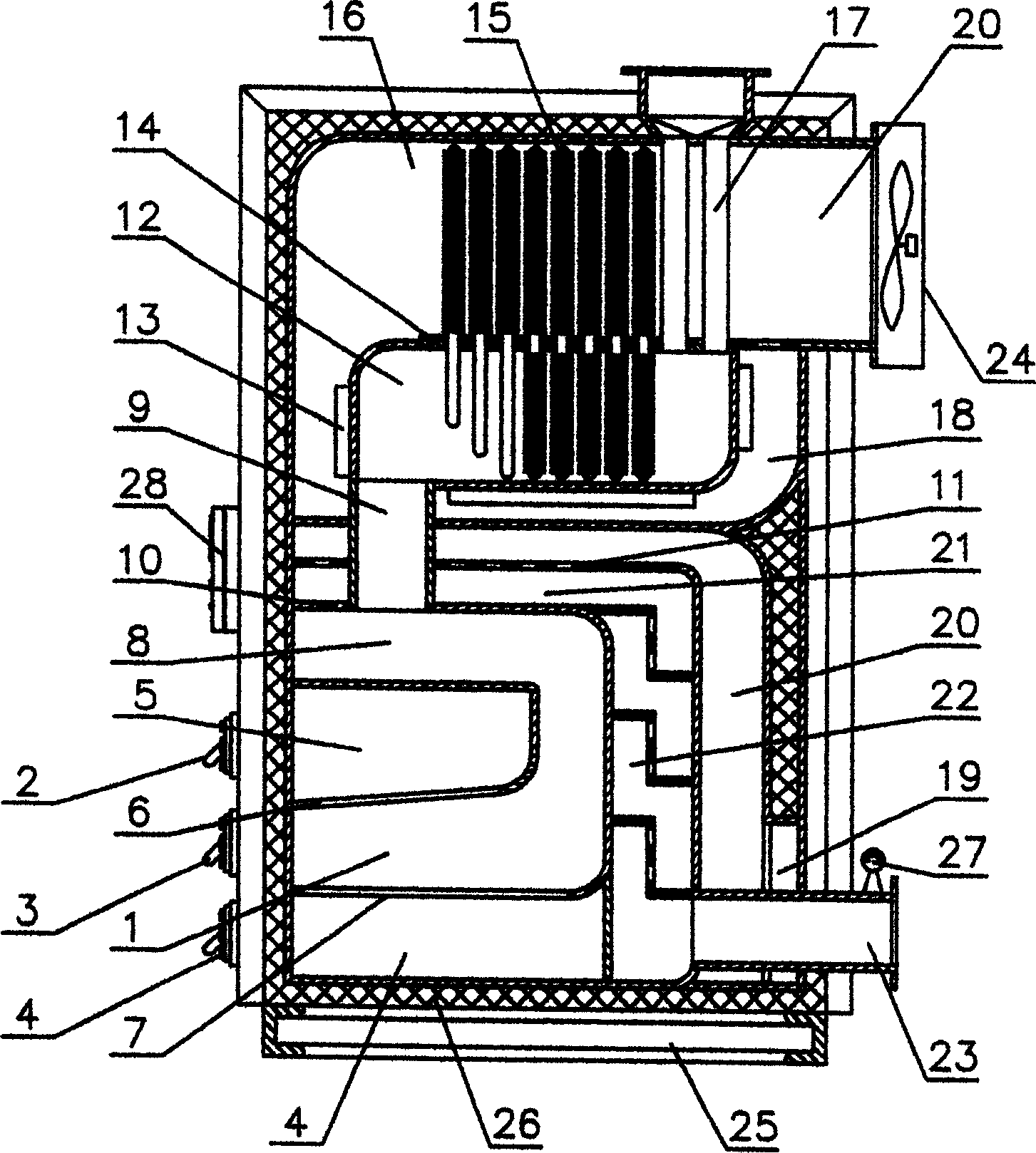
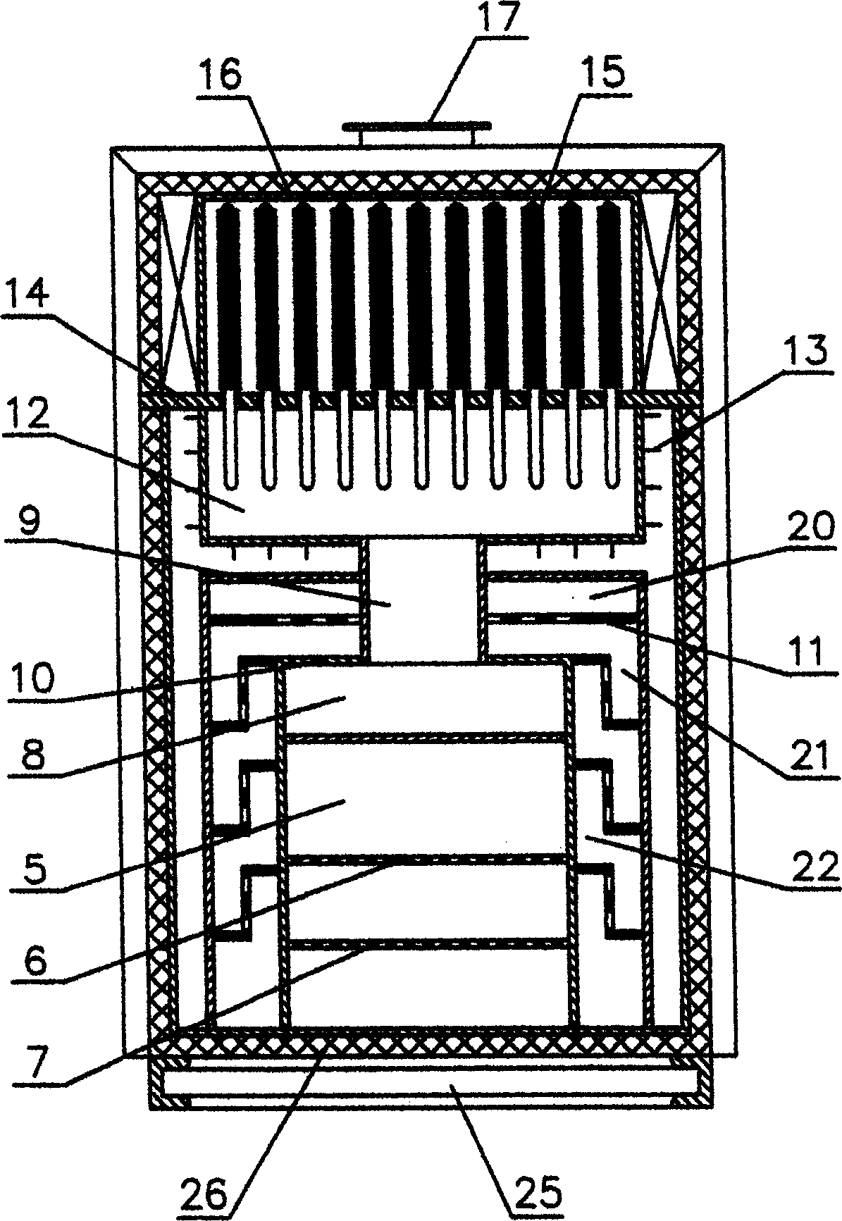
[0015] When the present invention was carried out, coal was added to the anti-burning fire grate (6) and the lower fire grate (7) from the coal charging door (2), and the coal was fully ignited with a fire material, and then the fire door (3) was closed and slightly opened. Open the slag door (4), open the coal feeding door (2), and at this time, the combustible gas is removed from the coal in the anti-burning grate (6) after dry distillation, and is ejected from the gap of the anti-burning grate (6) to ignite and burn , and the coal slag particles falling on the lower fire grate (7) continue to burn, and the combustion flame enters the fire path (8) radiation heating furnace ( 1) Plate, the top cover (10) enters the anti-fire channel to the flue (12) and flushes the flue (12) under the tube plate (14) and the heat-absorbing section of the heat pipe (15) in it, the heat pipe (15) The latent heat of vaporization is absorbed into the heat release section of the high-frequency we...


PUM


Abstract

The present invention relates to a double-layer back-combustion radiation jet heat-pipe hot-air furnace. It is a high-effective high-temp, novel hot-air indirectly-heating hot-air furnace which is made up by using heat-pipe heat-exchanger with high efficiency and small flow resistance and high-temp, radiation jet impact heat-exchanger with double-layer back-combustion furnace cavity by means of back flame path series-connection. Said invention also provides its concrete structure, its hot-air temperature can be up to 200-500deg.C and its heat efficiency can be up to about 85%.

Description

1 Technical field: [0001] The invention relates to a coal-fired heat source device for preparing hot air, which is widely used in technological occasions requiring hot air heating: wood drying and shaping, textile coating dyeing and finishing industry setting drying, rubber vulcanization, chemical industry polymerization, concentration and evaporation, Baking and curing of coating process, heating and drying of building materials industry, etc... 2 background technology: [0002] The existing coal-fired hot air stove adopts the furnace and tube structure, and relies on the gas-gas heat exchange of metal plates and tubes to heat the air. Due to the low heat transfer coefficient of the gas-gas heat exchange and the high temperature of the furnace wall, it affects For the safety and life of the hot blast stove, the use of a large-volume furnace increases the amount and cost of heat-resistant steel. At the same time, due to the temperature difference and stress of the tube plate...

Claims


Application Information

Patent Timeline
11 Jan 2006
Publication
CN1719151A
IPC
F24H3/00
Inventors
朱友良; 凌峰