
Method for integrating drying sludge using remaining heat of flume from power plant by rubbish and electricity generation using sludge

A technology for drying sludge and flue gas waste heat, which is applied in the directions of oxidation treatment sludge, dehydration/drying/thickening sludge treatment, sludge treatment through temperature control, etc., which can solve the problems of high cost and large amount, and achieve significant social and environmental benefits

Inactive Publication Date: 2006-02-15
ZHEJIANG UNIV
View PDF0 Cites 20 Cited by
  • Summary
  • Abstract
  • Description
  • Claims
  • Application Information

AI Technical Summary

Problems solved by technology

[0010] However, sewage treatment plant sludge and river dredging sludge are generally dehydrated by machinery, and the water content is generally between 75% and 85%. If the sludge is to be burned, the solid content of the sludge must first reach 100%. This means that a large amount of additional energy is required. The calculation based on the test shows that the sludge with a moisture content of 75% to 85% should be completely burned up, and the energy required to make the sludge reach the ignition point is greater than that generated by sludge combustion. energy, which is also the reason why sludge incineration and sludge treatment require high costs

Method used


Image

  • Method for integrating drying sludge using remaining heat of flume from power plant by rubbish and electricity generation using sludge

Examples


Embodiment 1

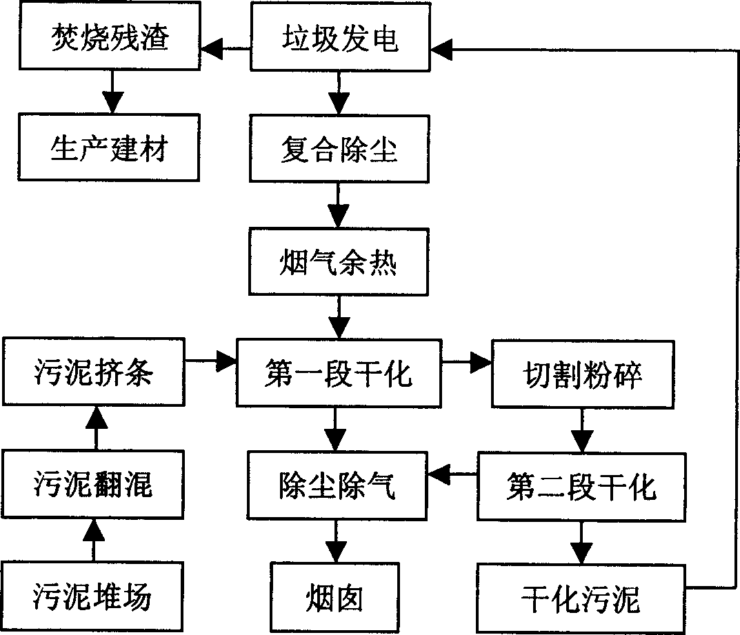
[0027] Example 1, Jiangsu Wuxi Waste-to-energy Plant, two existing waste incinerators are put into operation, and the amount of flue gas produced by each incinerator is 150,000m3 3 / hour, the waste heat temperature of the flue gas is about 150°C, and this technology is used to process 100 tons of urban sludge (with a moisture content of about 75%) per day. First, the sludge is pretreated in the stacking yard, part of the water is naturally evaporated, and the sludge is homogenized, and then the sludge is extruded into a column with a diameter of 8 mm through the extruder, and sent to the first rotary Drying kiln, use 100000m 3 The amount of flue gas per hour is carried out in the first stage of drying to reduce the moisture content of the sludge by 25%. After the sludge leaves the kiln, it passes through the cold conveyor belt and enters the second rotary drying kiln. 3 The amount of flue gas per hour, the second stage of drying reduces the moisture content of the sludge by 3...

Embodiment 2

[0028] Example 2, Zhejiang Garbage Power Plant, the amount of flue gas produced by waste incineration power generation is 130000m3 3 / hour, the waste heat temperature of the flue gas is about 130°C, and this technology can process 50 tons of urban sludge (with a moisture content of about 75%) per day. First, the sludge is pretreated in the stacking yard, part of the water is naturally evaporated, and the sludge is homogenized, and then the sludge is extruded into a column with a diameter of 8 mm through the extruder, and sent to the first rotary Drying kiln, with 80000m 3 The amount of flue gas per hour is dried in the first stage to reduce the moisture content of the sludge by 20%. After the sludge leaves the kiln, it passes through the cold conveyor belt and enters the second rotary drying kiln. 3 The amount of flue gas per hour, the second stage of drying reduces the moisture content of the sludge by 33%, and the sludge after the second stage of flue gas waste heat drying...


PUM


Abstract

The invention discloses an integrative method to use residue heat of garbage power plant to dry sludge and generate electricity by sludge, which comprises: 1) removing dust to the discharged smoke gas and drying sludge with two-stage; 2) pretreating the sludge from urban sewage disposal plant, or dredged sludge; 3) processing the pretreated sludge into column shape by machine for first drying stage; 4) cutting the said sludge out of kiln into particle; 5) taking second drying stage to sludge particle of size less than 6-10mm; 6) conveying the sludge to garbage electricity generating system to mix with garbage and coal and burn for electricity. This method has well social, environmental and economic benefits.

Description

technical field [0001] The invention relates to a method for integrating drying sludge with waste heat of flue gas from a garbage power plant and generating electricity from the sludge. Background technique [0002] In order to protect our limited water resources and create a good living environment, domestic sewage and industrial wastewater must be treated by sewage treatment plants, and can only be discharged after reaching the national sewage discharge standards. Whether there is an urban sewage treatment system has become a modern urban civilization. It is also an indispensable environmental engineering measure for urban ecological environment construction. The urban sewage treatment system includes two parts: sewage treatment and sludge treatment. In recent years, through the introduction of foreign advanced technology and technological transformation, my country's water treatment technology level has been greatly improved, and various types of sewage can be effectivel...

Claims


Application Information

Patent Timeline
IPC IPC(8): C02F11/12C02F11/18C02F11/06
CPCY02W10/40
Inventor 翁焕新苏闽华
Owner ZHEJIANG UNIV
Learn More