In site detecting method for building wall heat transfer coefficient

A heat transfer coefficient and building wall technology, which is applied in the field of on-site detection of building wall heat transfer coefficient, can solve problems such as difficulty in finding a suitable test site, equipment adaptability to a large site, and a large heat box to achieve shortening Test time, facilitate on-site installation and use, and enhance the effect of adaptability

Inactive Publication Date: 2007-01-24
上海市房地产科学研究院
View PDF0 Cites 28 Cited by
  • Summary
  • Abstract
  • Description
  • Claims
  • Application Information

AI Technical Summary

Problems solved by technology

Therefore, this method also has certain requirements on the temperature difference between indoor and outdoor, and requires the test time to be more than 72 hours. At the same time, the hot box used in this method is huge (

Method used


Image

  • In site detecting method for building wall heat transfer coefficient
  • In site detecting method for building wall heat transfer coefficient

Examples


Example Embodiment

[0026] Embodiment one:

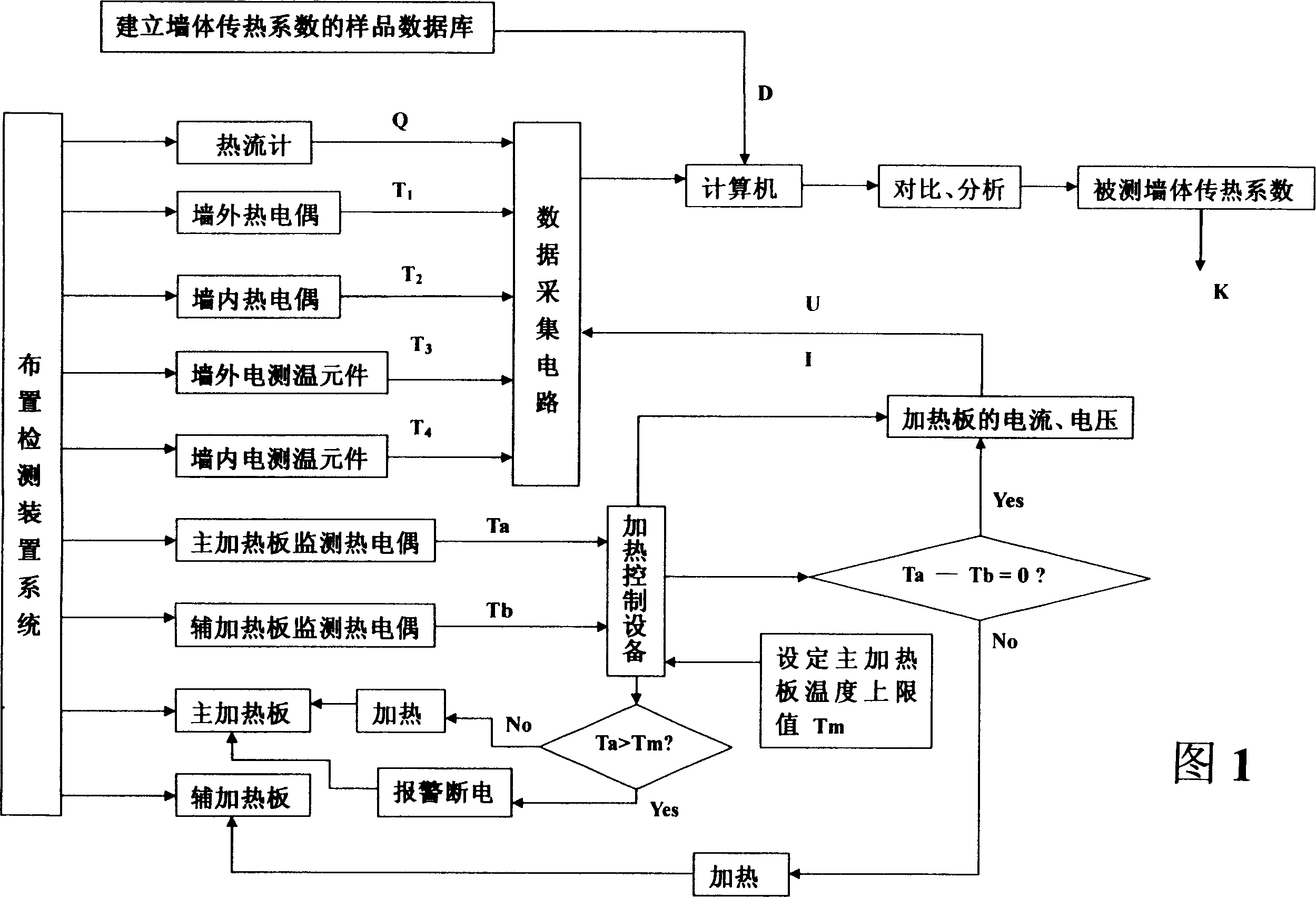
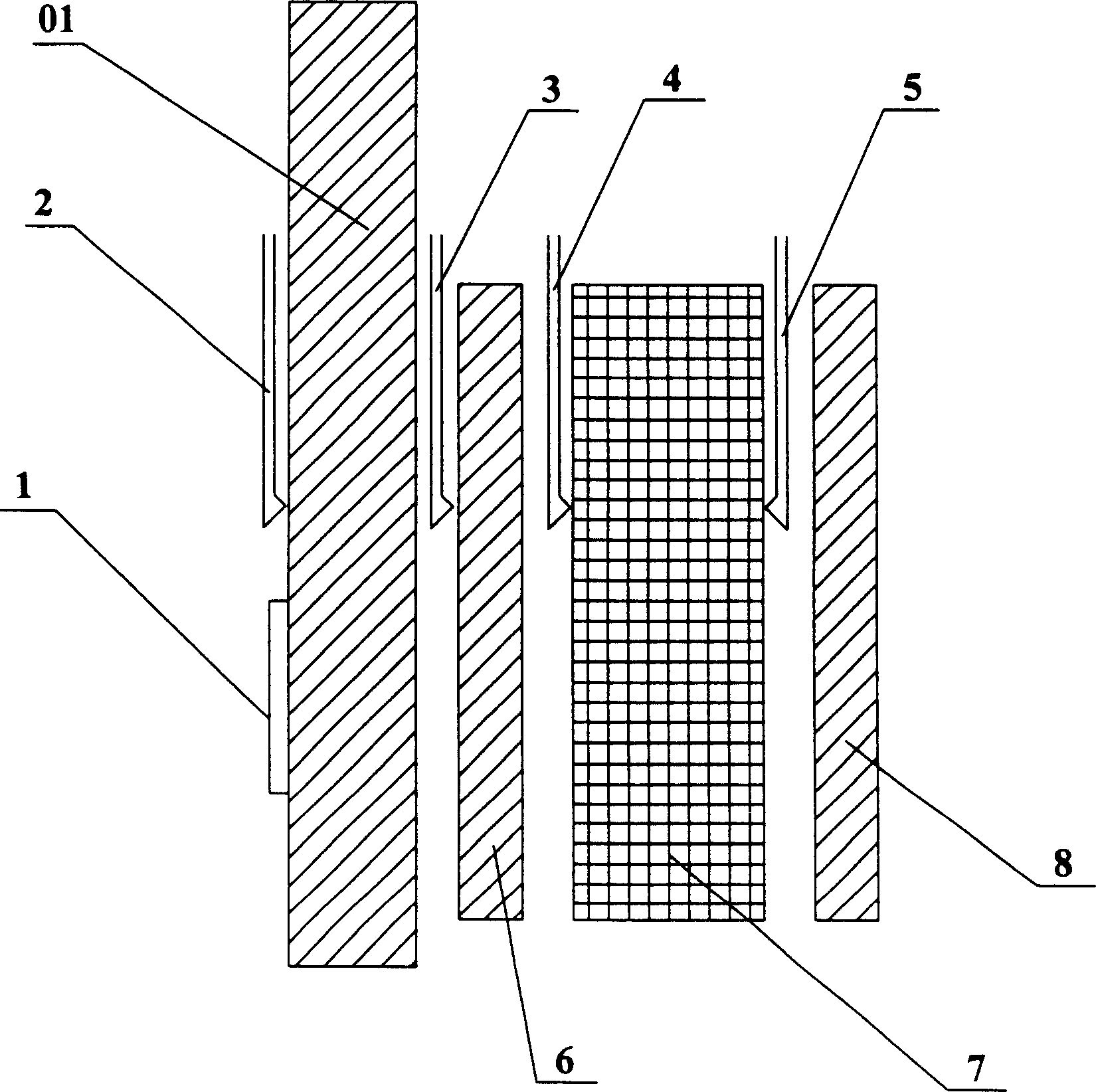
[0027] 1. Layout system: The tested wall 01 is composed of 20mm thick mixed mortar plaster, 240mm thick hollow clay brick wall, 20mm thick cement mortar, 50mm thick polystyrene board insulation layer and 10mm thick mixed mortar plastered surface. The measurement area is determined to be 400mm×400mm, the length and width of the main heating plate 6 and the auxiliary heating plate 8 are both 400mm, the thickness is 30mm, the output power is 32W, the thickness of the heat insulation plate 7 is 100mm, and the material is epoxy resin. The thermocouple 2 outside the wall is arranged with There are 9 thermocouples in the wall 3, and there are 7 thermocouples in the wall. The electric temperature measuring elements inside and outside the wall use thermal resistance, the inner layer of the heating device shell is made of thermal insulation cotton material, and all thermocouples are copper-constantan thermocouples. There is sample database D.

[0028] 2. Heatin...

Example Embodiment

[0032] Embodiment two:

[0033] 1. Layout system: The tested wall 01 is composed of 20mm thick mixed mortar plaster, 240mm thick hollow clay brick wall, 20mm thick cement mortar, 15mm thick polyurethane board insulation layer and 10mm thick mixed mortar plastered surface. The area is determined to be 400mm×400mm, the length and width of the main heating plate 6 and the auxiliary heating plate 8 are 400mm, the thickness is 30mm, the output power is 45W, the thickness of the heat insulation plate 7 is 100mm, and the material is epoxy resin. There are 7 thermocouples 3 arranged in the wall, thermometers are used for temperature elements inside and outside the wall, plastic foam material is used for the inner shell of the heating device, copper-constantan thermocouples are used for all thermocouples, and samples are stored in the computer. databaseD.

[0034] 2. Heating: Set the temperature upper limit Tm of the main heating plate 6 to 90° C., set the voltage U of the main heatin...


PUM

PropertyMeasurementUnit
Heat transfer coefficientaaaaaaaaaa

Abstract

Using heater and control unit carries out constant heating for wall body to be tested by using plane heat source in ordinary power so as to form a local steady even heat flow in area to be measured. Thus, wall body is tested under manmade steady heat transfer state. Then, temperatures inside and outside wall, heat-flow density and ambient air temperature is itinerant connected. The said heat-flow density is heat-flow density passing through external surface of wall from inside wall to outside wall in area to be tested. Then, comparison and analysis are carried out between the collected data and sample database of heat transfer coefficient of wall body stored in computer and built in advance so as to obtain heat transfer coefficient of wall body finally. Advantages are: preventing influences from surrounding weather, and heat storage and emission of wall body self, good adaptability to climatic environment, short test time, high precision, low cost etc. The invention is suitable to southward with low difference in temperature between indoor and outdoor.

Description

Technical field: [0001] The invention relates to building detection, in particular to an on-site detection method for building wall heat transfer coefficient. Background technique: [0002] As a large country with rapid economic development, China's demand for energy is increasing day by day. Especially in recent years, the contradiction between economic growth and energy constraints has become more and more prominent. "Energy saving" has become the top priority of my country's national economic development. Building energy consumption occupies a large proportion of the total energy consumption in our country, and it is increasing year by year. Therefore, building energy conservation is one of the key points of energy conservation work in our country. A large number of new energy-saving buildings are completed in my country every year. These energy-saving buildings are generally constructed in accordance with the requirements of national and local building energy-saving desi...

Claims


Application Information

Patent Timeline
IPC IPC(8): G01N25/20E02D33/00
CPCG01K17/20
Inventor 林驹李娟娟王宝海陈秀芬朱彤赵为民赵鸿金桂华
Owner 上海市房地产科学研究院
Why Eureka
Try Eureka