Fuel cell, electronic equipment, movable body, power generation system and cogeneration system

A fuel cell and fuel technology, applied in the direction of fuel cells, biochemical fuel cells, solid electrolyte fuel cells, etc., can solve the problems of resource consumption, high temperature heating, difficult practical application, etc., to simplify the fuel supply system, realize resource recycling society, easy to handle effects

Inactive Publication Date: 2007-07-04
SONY CORP
View PDF3 Cites 11 Cited by
  • Summary
  • Abstract
  • Description
  • Claims
  • Application Information

AI Technical Summary

Problems solved by technology

However, fuel cells have various problems: fuel cells generally use hydrogen converted from natural gas, petroleum, or coal by a reformer as fuel, and thus consume limited resources and require high-temperature heating, and fuel cells need to contain ma...

Method used


Image

  • Fuel cell, electronic equipment, movable body, power generation system and cogeneration system
  • Fuel cell, electronic equipment, movable body, power generation system and cogeneration system
  • Fuel cell, electronic equipment, movable body, power generation system and cogeneration system

Examples


Embodiment 1

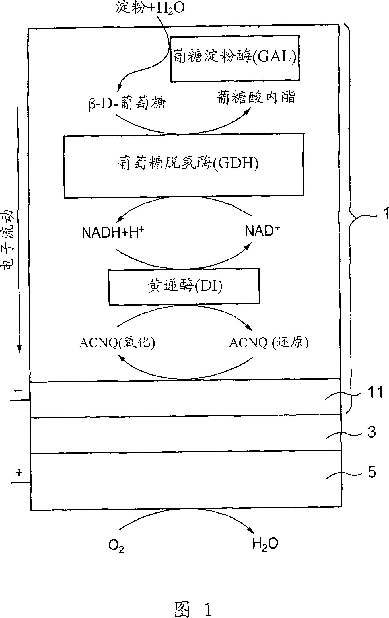
[0127] 3 μl of diaphorase (DI) (UNITIKA LTD., from Bacillus stearothermophilus) in phosphate buffered saline (83 μM), 6 μl of glucose were applied dropwise on a glassy carbon (GC) electrode (BAS, φ=3.0 mm). Dehydrogenase (GDH) (TOYOBO LTD.) in phosphate buffered saline (60 μM), 3 μl of glucoamylase (GAL) (Oriental Yeast Co., Ltd.) in phosphate buffered saline (1.4 mM), 3 μl of poly- L-lysine (PLL) in water (1%), 2 μl of NADH in phosphate buffered saline (0.4 M), 2 μl of ACNQ in ethanol (28 mM) and 3 μl of glutaraldehyde (GA) in water (0.125%), and They were mixed with each other and air-dried at room temperature, and then washed with distilled water to prepare a GAL / GDH / NADH / DI / ACNQ immobilized electrode (see FIG. 1 ).

[0128] The immobilized electrode prepared in this way is used as a working electrode, the Ag / AgCl electrode is used as a reference electrode, the Pt electrode is used as a pole plate, and the electrolytic cell made of polytetrafluoroethylene with a volume of 1...

Embodiment 2

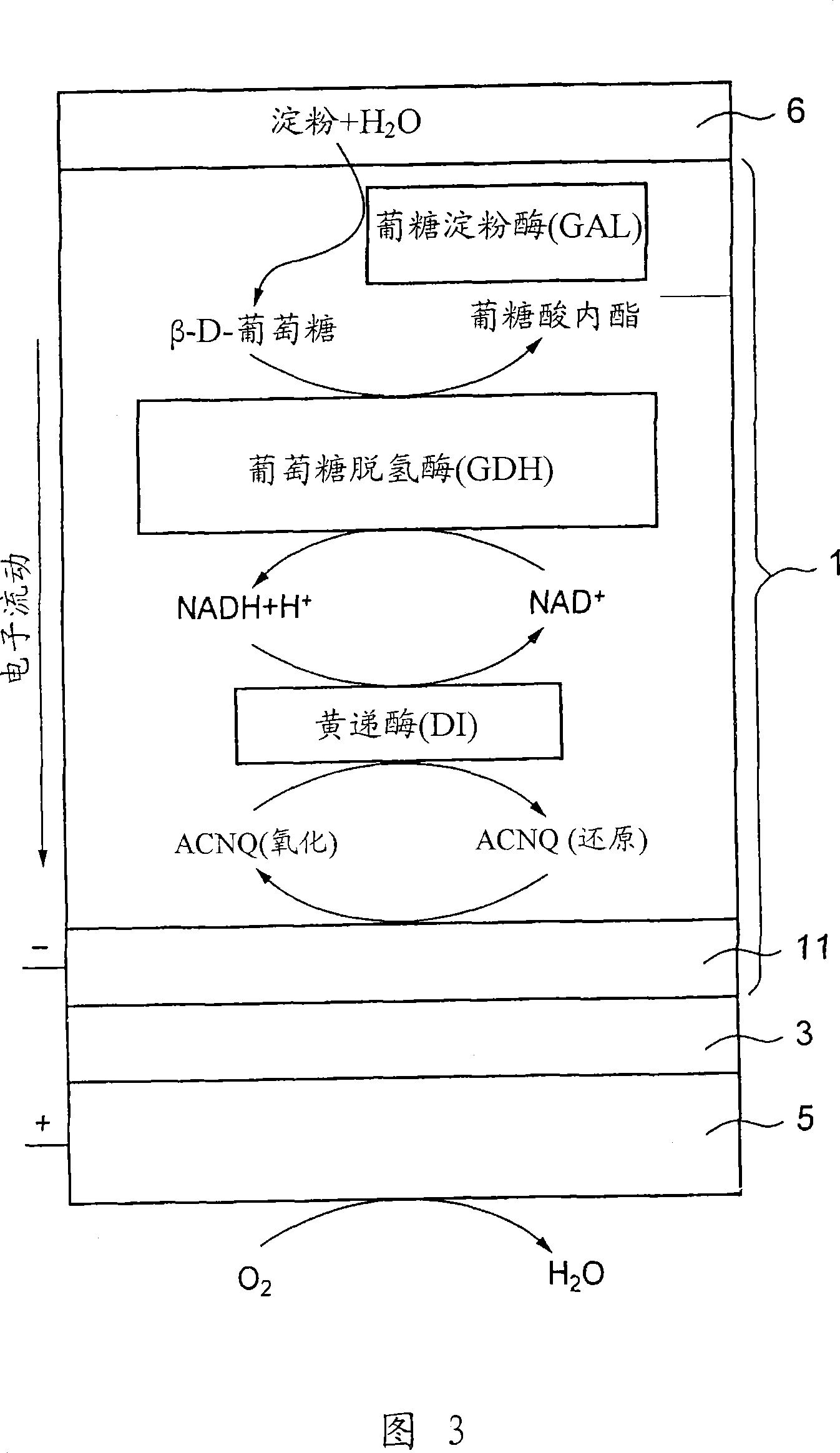
[0130] Electrochemical measurements were performed in substantially the same manner as in Example 1, except that 5 mg of the substance obtained by gelatinizing a 50% starch phosphate buffer solution at 70° C. was coated on the GAL / GDH / NADH / DI prepared in Example 1 / ACNQ was immobilized on the electrode, and the reaction solution was changed to 1 ml of 0.1 M phosphate buffer solution (pH 7; I.S.=0.3).

Embodiment 3

[0140] For the fuel electrode 1 having starch gel 6 immobilized thereon as fuel and glucoamylase (GAL) as decomposing starch into glucose, CV measurement was performed under the same conditions as used in Example 1. The results are shown in Figure 12 (curve a). In FIG. 12 , as a reference, the CV measurement results (curve b) in the case where the glucose solution is used as fuel are also shown. As can be seen from FIG. 12 , compared with the maximum current obtained when glucose solution (glucose concentration: 200 mM) was used as fuel, when starch glue 6 was used as fuel, a considerable current could be obtained. As mentioned above, this result indicates a very high concentration of glucose on the electrode 1 surface. In addition, the reason why the current increases with the lapse of time is that starch is gradually hydrolyzed by glucoamylase (GAL), and thus the concentration of glucose on the electrode surface increases with the lapse of time. Curve b has a shape only fo...


PUM

PropertyMeasurementUnit
Current densityaaaaaaaaaa
Power densityaaaaaaaaaa

Abstract

A fuel cell capable of directly abstracting electric power from polysaccharides, such as starch. Fuel electrode (1) is produced by fixing on electrode of carbon, etc. (11) by means of a fixative an enzyme participating in decomposition of polysaccharides to monosaccharides, an enzyme participating in decomposition of formed monosaccharides, a coenzyme (e.g., NAD<+>, NADP<+>, etc.) whose reduced form is produced in accordance with an oxidation reaction during the process of monosaccharide decomposition, a coenzyme oxidase (e.g., diaphorase) capable of oxidizing the reduced form of coenzyme (e.g., NADH, NADPH, etc.), and an electron mediator (e.g., ACNQ, vitamin K3, etc.) capable of receiving electrons generated by the coenzyme oxidation from the coenzyme oxidase and delivering the same to the electrode (11). The fuel electrode (1) is disposed opposite to air electrode (5) through electrolyte layer (3) to thereby construct a fuel cell.

Description

technical field [0001] The present invention relates to fuel cells, electronic devices, movable bodies, power generation systems, and combined heat and power systems using enzymes as catalysts. Background technique [0002] A fuel cell basically consists of a fuel electrode (negative electrode), an oxidant electrode or an air electrode (positive electrode), and an electrolyte (proton conductor), and has a working principle based on the reverse reaction of electrolyzing water so that hydrogen and oxygen react to form water (H 2 O) and generate electricity. Specifically, the fuel (hydrogen) supplied to the fuel electrode is oxidized and decomposed into electrons and protons (H + ), and the electrons go to the fuel electrode, while the protons H + Move through the electrolyte to the oxidant electrode. At the oxidant electrode, the proton H + Reacts with oxygen supplied from the outside and electrons supplied from the fuel electrode through an external circuit to generate H ...

Claims


Application Information

Patent Timeline
IPC IPC(8): H01M8/16H01M4/86H01M8/06H01M8/10
CPCY02E60/521Y02E60/527Y02E60/50
Inventor 酒井秀树富田尚佐藤敦户木田裕一
Owner SONY CORP
Why Eureka
Try Eureka