
Method for producing a steel shaped body

a technology of steel shaped bodies and shaped bodies, which is applied in the direction of metal-working apparatuses, transportation and packaging, etc., can solve the problems that the production of bainitically formed steel shaped bodies has an intrinsically pronounced stability, and the prior art does not explicitly relate to the production of bainitically formed steel shaped bodies. achieve the effect of increasing the static strength of the shaped body formed at the end of the inventive method

Active Publication Date: 2019-03-05
ROBERT BOSCH GMBH
View PDF22 Cites 0 Cited by
  • Summary
  • Abstract
  • Description
  • Claims
  • Application Information

AI Technical Summary

Benefits of technology

The invention relates to a method for producing a high-tensile steel shaped body with advanced mechanical properties, such as high strength and ductility, through powder injection molding. The method involves using a predefined powder composition containing iron oxide and micro-alloy elements to adjust the bainitic phase during the process. The resulting shaped body is slow in conversion due to its chemical composition, allowing for the production of a bainitic microstructure with advantages such as high mechanical strength and ductility. The method can be used for producing structural components, such as fuel injection valves, with reduced post-processing effort and cost savings. Additionally, the method can be enhanced by the addition of superfine-grained oxide ceramic particles formed from chemical compounds like zirconium oxide, silicon oxide, aluminum oxide, yttrium oxide, silicon nitride, or silicon carbide to increase the static strength of the shaped body.

Problems solved by technology

This prior art, however, does not explicitly relate to the production of bainitically formed steel shaped bodies having an intrinsically pronounced stability.

Method used


Image

  • Method for producing a steel shaped body
  • Method for producing a steel shaped body

Examples


Embodiment Construction

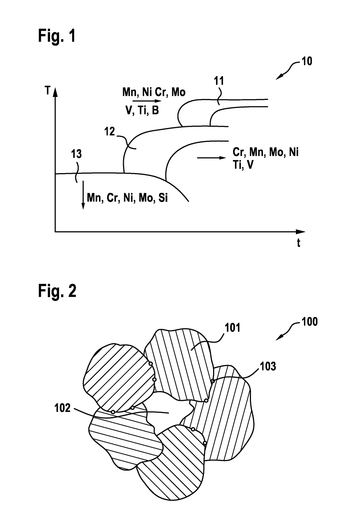
[0014]FIG. 1 illustrates the operating principle of the method according to the invention using a schematically depicted state diagram 10. The temperature profile for the essential state ranges of steel is plotted on the ordinate axis of said state diagram 10 versus the cooling period extending along the abscissa axis thereof. The ferrite-perlite state range 11 is depicted in the upper temperature range of the state diagram 10, the bainite state range 12 in the middle temperature range and the martensite state range in the lower temperature range. The mechanism of action according to the invention now consists of forming a powderous composition which is based on iron oxide, for example Fe3O2, by means of the addition of metal oxides such as nickel oxide or molybdenum oxide as well as by means of the addition of metallic powder such as chrome and in which composition, during sintering, the phase transformation from the austenite to the ferrite-perlite state range 11 is suppressed or ...


PUM

PropertyMeasurementUnit
temperatureaaaaaaaaaa
microstructureaaaaaaaaaa

Abstract

The invention relates to a method for producing a steel shaped body, particularly, for example, a component for common rail fuel injection valves, comprising the method steps of: forming a powderous composition based on iron oxide, from oxide particles, with the addition of carbon and micro-alloy elements so as to adjust a bainitic microstructure; heating the powderous composition to a sinter temperature; reducing the shaped body obtained by sintering; and cooling the sintered shaped body to room temperature. As a result, from the three essential state phases in a state diagram (10), specifically the ferrite-perlite state range (11), the bainite state range (12) and the martensite state range (13), preferably the bainitic state phase is formed in a medium temperature range by the ferrite-perlite state range (11) being shifted to longer cooling periods and the martensite state range (13) being shifted to lower temperatures.

Description

BACKGROUND OF THE INVENTION[0001]The invention relates to a method for producing a steel shaped body, particularly, for example, a component for common rail fuel injection valves.[0002]Steel blanks can be produced by means of smelting metallurgy methods. The raw material in the steel plant consisting of pig iron is smelted via the LD-route or consisting of scrap iron via the so-called electric furnace route, and the desired composition is thereby adjusted in the molten state. After that smelting process, such a steel blank is continuously cast to precursor material in continuous casting plants, which is subsequently rolled out to bar steel in the rolling mill using thermomechanical rolling technology with or without heat treatment subsequently taking place in a targeted manner. The bar steel is then used as the starting material for the metal-cutting manufacturing of corresponding components.[0003]Near-net-shape manufacturing processes, with which metallic components can be produced...

Claims


Application Information

Patent Timeline
Patent Type & Authority Patents(United States)
IPC IPC(8): B22F3/10C22C33/02B22F1/00B22F5/00B22F1/102B22F1/103
CPCB22F3/10B22F1/0062B22F3/1003B22F3/1021B22F3/1039B22F5/00C22C33/0264B22F2999/00B22F2302/256B22F2302/253B22F2302/25B22F2001/0066B22F2301/35B22F2302/105B22F2302/20B22F2201/32B22F2201/02B22F2201/016B22F1/103B22F1/102
Inventor LANGNER, HEIKE
Owner ROBERT BOSCH GMBH
Learn More