Maximal modifiable modular capacitor generator (CAPGEN)

Active Publication Date: 2019-04-23
TARTIVITA SANTO ROMANO
View PDF10 Cites 5 Cited by
  • Summary
  • Abstract
  • Description
  • Claims
  • Application Information

AI Technical Summary

Benefits of technology

[0072]All strata may be contained in an electron attractor and electron collector metal canister; i.e. selenium, germanium and other elements from the periodic table. Even more advantage may be gained by encapsulating all inner strata in a canister with the inner surfaces coated with a radiant emitting element-compound, i.e. thorium.
[0073]Still more advantage may be gained when the canister cathode electrode outer surface is coated with a modified photovoltaic activated carbonaceous powder and protected from the environment with a transparent film i.e. glass, polymers etc.

Problems solved by technology

When conductive binders (electrolytes) are used as binders to form carbon electrodes, the capacitor internal electrical resistance decreases and the capacitance increases but the working voltage and amperage are severely limited.
Glassy carbon electrodes have better structural characteristics but require conventional electrolytes to enhance the electrode's capacitance thereby severely limiting the charging voltage.
The low voltage severely limits the electrical storage capacity of the capacitor.
However, high capacitance was achieved at the expense of limiting the working voltage to 0.9V and the current density to 300 mA / cm2.
Ceramic dielectric materials of this type are extremely fragile due to the dielectric thinness, thermal stress and expansion-contraction cycles, therefore each capacitor in the above patent was limited to an area of only 0.5806 cm2.
It is problematic that 31,331,000 extremely thin ceramic capacitors at 3500V can function for years without degradation and malfunction and that damaged capacitors can be located and repaired economically.
A significant factor is that conventional electrolytes limit the test voltage to 3V and a small change in charge from 3V to 2.8V severely decreases the capacitor's energy density.
However, to date there is not a radiation conversion system that generates sufficient power that is economical, portable and can power an automobile for a few miles.
Some of the limiting factors to generate greater electrical current output from this technology and to be used for general purposes are:1. Electric energy is generated by thermionic (heat) emission only.2. The total energy is limited to a few hundred watts.3. Due to hundreds or thousands of thermocouples connected in series, electrical resistance increases limiting the electrical output.4. Since the thermocouples are metallic, their combined weight becomes burdensome.5. To assemble the thermocouples multitude it becomes cumbersome and time consuming.6. The cost per watt is prohibitive for most practical uses.
The water, being in proximity to the nuclear fuel, becomes radioactive and a major safety concern.
Due to a multitude of systems, such as containment structure, pressurized structure, reactor container, steam generator, steam turbine, condensers, electric generator, pumps, vapor chimney tower, a large supply of water etc. the entire system becomes necessarily complicated, fastidious, expensive and nerve racking to the general public.
Once electricity is generated, approximately 30% of it is wasted in transmission lines before it gets to the consumer.
The spent nuclear byproducts become a major problem as to where to store it, how and for how long to store it and for unknown future cost or problems such as decommissioning the entire plant.
To date no practical portable pebble-bed gas reactor or nuclear plant exists to generate electricity directly-without moving parts or to propel a motor vehicle a few miles.
Nuclear power plants' waste materials currently are stored at great cost, in large water tanks, metal or concrete vaults usually at the same site where they are generated.
The present science in CAPBAT does not solve the practical problem of storing sufficient electrical energy to economically propel motor vehicles for long distances per charge and charge the unit in minutes or seconds.

Method used


Image

  • Maximal modifiable modular capacitor generator (CAPGEN)

Examples


example 1

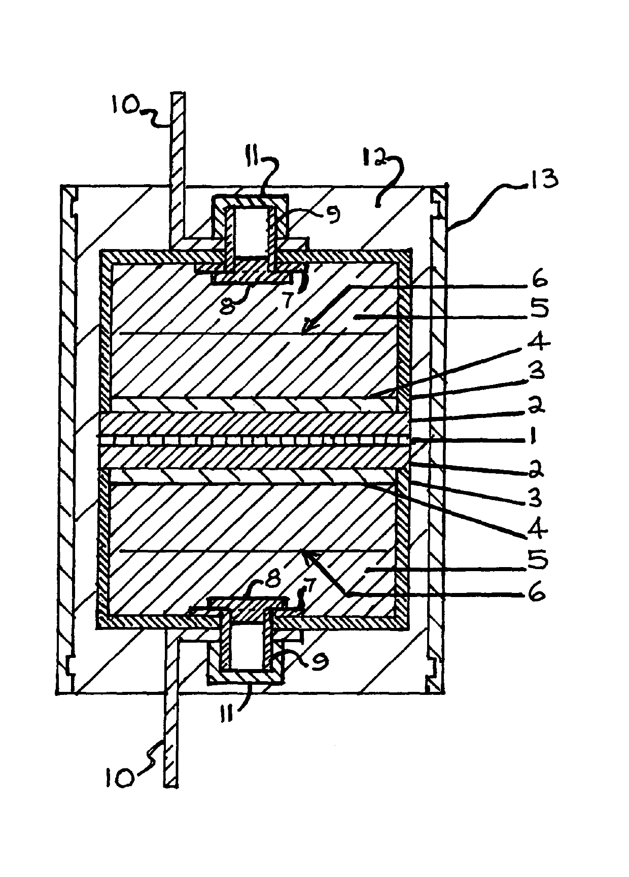
[0122]One of the fundamental and exemplary base capacitors architecture as described in the first embodiment above and further described herein has the following attributes: contains an inner capacitor (A) with a perforated ceramic separator 1 sandwiched between two inner perforated metal electrodes 2 that are bonded between two perforated metal-filtered canister carbon electrodes 3 as described therein in (A) and (B). Each canister 3 electrode contains 500 g of activated carbon powder 5 with 2500 m2 / g surface area, the interior canister carbon electrodes 3 are reticulated with metal grids 6 (the same material as canister 3) and compacted at 1 cm intervals from 0-20 Kg / cm2. Thereafter, the capacitor interior air is rarefied (electrolyzed) to approximately 10 TORR to obtain maximal internal electrical conductivity and minimal internal electrical resistance at high voltage. The total capacitor weight is approximately 3 kg or 7.6 lbs. The capacitor described herein is charged arbitrari...


PUM

PropertyMeasurementUnit
temperaturesaaaaaaaaaa
voltageaaaaaaaaaa
current densityaaaaaaaaaa

Abstract

A maximal modifiable modular capacitor-generator (CAPGEN) architecture, dielectrics and electrodes may be modified and retain substantially all of the starting activated carbon powder surface area by encapsulating the activated carbon powder in a modifiable gaseous medium and pressure. The capacitor electrical conductivity may be further increased and resistance reduced by electrically reticulating the electrodes and/or modifying the carbon electrode with rarefied or pressurized gases, conventional electrolytes, radioisotopes, stratified radiation emitting materials such as gases, liquids, solids, or modified photovoltaic carbon powder, thereby the capacitor becomes self charging and the surface area, mass, voltage, capacitance, energy density, power density and working temperature are maximized so that the same capacitor base architecture may be maximally modified from a capacitor to a CAPGEN, to a photovoltaic-thermionic CAPGEN and helium generator.

Description

CROSS REFERENCE TO RELATED APPLICATIONS[0001]Not applicable.STATEMENT REGARDING FEDERALLY SPONSORED RESEARCH OR DEVELOPMENT[0002]Not applicable.BACKGROUND OF THE INVENTION[0003]The object of this invention is to create a modifiable modular capacitor-generator (CAPGEN) base architecture capable of directly converting and storing a multitude of energies; i.e. 1. (VACUA) V power, gases, space photons, spent nuclear fuels, thermionic heat, electrolytes etc. 2. replace a multitude of conventional batteries with low voltage and high capacitance per Kg, 3. replace a multitude of conventional capacitors with high voltage and low capacitance per Kg, 4. combine capacitors best quality (power density) with batteries best quality (energy density) in a single new modifiable modular CAPGEN architecture with revolutionary electrolytes, massive electrodes, 5. new methods to increase electrical conductivity and reduce electrical resistance, 6. generates its own primary and secondary electrical charg...

Claims


Application Information

Patent Timeline
Patent Type & Authority Patents(United States)
IPC IPC(8): H01G11/42G21H1/00H01G9/004
CPCH01G11/42H01G9/004G21H1/00H01G11/14H01G11/24H01G11/26H01G11/32H01G11/82
Inventor TARTIVITA, SANTO ROMANO
Owner TARTIVITA SANTO ROMANO
Why Eureka
Try Eureka