Hydrogen generator

a technology of hydrogen generator and generating apparatus, which is applied in the direction of sustainable manufacturing/processing, final product manufacturing, and separation processes. it can solve the problems of low ammonia decomposition rate, high production apparatus cost as a whole, and deactivation of catalysts, so as to reduce the cost of production apparatus and achieve the effect of efficient decomposition of source gas into hydrogen, high yield and convenient us

Active Publication Date: 2020-03-03
SAWAFUJI ELECTRIC COMPANY +1
View PDF10 Cites 1 Cited by
  • Summary
  • Abstract
  • Description
  • Claims
  • Application Information

AI Technical Summary

Benefits of technology

[0015]With the hydrogen separation membrane arranged between the source gas flow channel and the hydrogen flow channel, the hydrogen generating apparatus according to the embodiment of the present invention is capable of transforming source gas into plasma in a uniform manner by causing an electric discharge in the source gas flow channel located between the hydrogen separation membrane and the electrode. Moreover, the hydrogen generated by plasma transformation in the source gas flow channel passes through the hydrogen separation membrane and is directly introduced into the hydrogen flow channel. It is therefore possible to efficiently decompose the source gas into hydrogen and separate the generated hydrogen from the source gas to generate hydrogen at a high yield.
[0016]In the hydrogen generating apparatus according to the embodiment of the present invention, the source gas flow channel is a groove in the form of a plurality of channel sections extending in a straight or a curved line and a plurality of return channel sections extending back from the channel sections, the channel sections and return channel sections being connected alternating with one another, and the hydrogen separation membrane is arranged facing the first surface of the dielectric body so as to seal the opening of the source gas flow channel groove. This way, the electric discharge between the hydrogen separation membrane and the electrode will occur transverse to the flow direction of the source gas. As a result, it is possible to supply electric power to the source gas in the hydrogen flow channel for a long time, such that the source gas can be transformed into plasma in a uniform manner more efficiently.
[0017]In the hydrogen generating apparatus according to the embodiment of the present invention, the tabular dielectric body, the electrode, the hydrogen flow channel plate, and the hydrogen separation membrane can be integrated into a single module. Combining several hydrogen generating apparatuses according to the embodiment of the present invention in parallel allows for flexible handling of changes in the amount of hydrogen to be supplied, and also eases conditions for suitable places of installation.
[0018]Depending on the required amount of hydrogen to be generated, the dielectric body of the hydrogen generating apparatus according to the embodiment of the present invention can be easily be modified, possible modifications including the cross-sectional shape of the recess constituting the source gas flow channel, the total length of the source gas flow channel, the source gas flow channel's contact surface with the hydrogen separation membrane, the supply rate of the source gas, and the like.

Problems solved by technology

However, steam reforming requires processing at high temperatures using expensive catalysts such as nickel, which makes the production apparatus expensive as a whole.
Moreover, when the mole ratio of steam to the carbon contained in the hydrocarbon used as raw material becomes low, coking of the carbon on the catalyst occurs, which deactivates the catalyst.
However, such catalysis methods have a low decomposition rate of the ammonia, and cannot generate hydrogen pure enough for use in fuel cells at a high yield.
Larger reactors could therefore actually be less energy efficient than smaller ones, and there was therefore a risk of a reduced hydrogen yield when large-scale production of hydrogen was necessary.

Method used


Image

  • Hydrogen generator
  • Hydrogen generator
  • Hydrogen generator

Examples


example 1

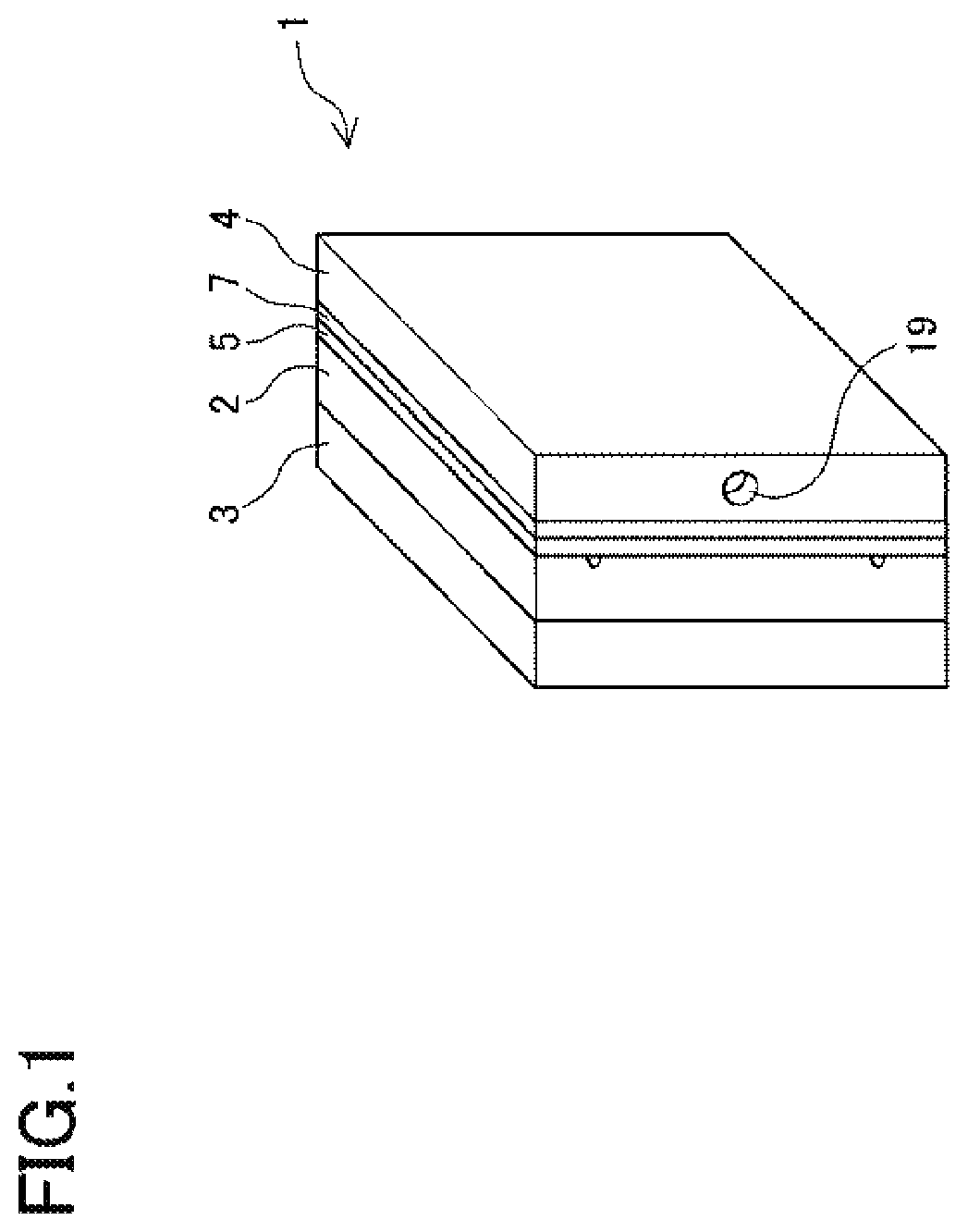
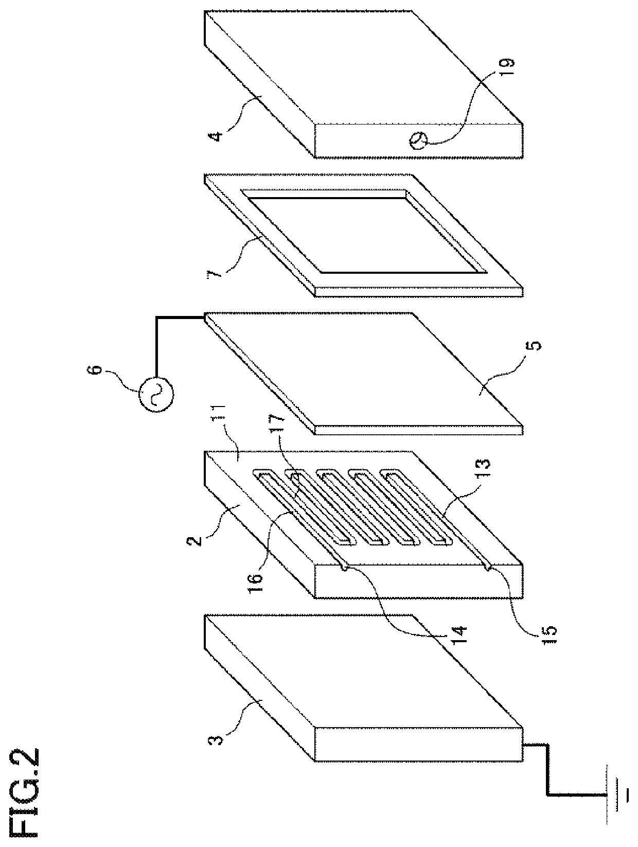
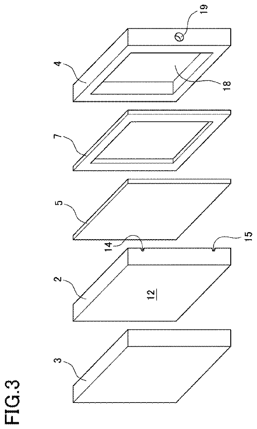
[0038]A preferred example of the hydrogen generating apparatus according to the present invention is described below with reference to the drawings. FIG. 1 is a schematic perspective view of the hydrogen generating apparatus 1 according to the present example. FIG. 2 is an exploded perspective view of the front, top, and right faces of the elements of the hydrogen generating apparatus 1. FIG. 3 is an exploded view of the front, top, and left faces of the elements of the hydrogen generating apparatus 1. The hydrogen generating apparatus 1 includes a dielectric body 2, an electrode 3, a hydrogen flow channel plate 4, a hydrogen separation membrane 5, a high-voltage power supply 6, and an insulating spacer 7. In the following descriptions, the surfaces of the elements shown on the right side of FIGS. 1 to 4 will be referred to as the right side surfaces. The right side surface of the dielectric body 2 corresponds to a first surface 11 of the dielectric body 2. Likewise, the surfaces of...

example 2

[0053]FIG. 6 shows a hydrogen generating apparatus 41 according to the present example. In the hydrogen generating apparatus 41, the hydrogen separation membrane 5 is grounded and functions as a grounding electrode. Meanwhile, the electrode 3 is connected to the high-voltage power supply 6 and functions as a high-voltage electrode. An insulating spacer 9 is arranged on the outside of the electrode 3. In the present example, the high-voltage power supply 6 applies a voltage to the electrode 3 to cause dielectric barrier discharge in the source gas flow channel 13 between the hydrogen separation membrane 5 and the electrode 3. This discharge transforms the ammonia in the source gas flow channel 13 into atmospheric pressure non-equilibrium plasma, making it possible to generate hydrogen at a high yield and separate it as high-purity hydrogen by the hydrogen separation membrane 5 for supplying to an external device.

example 3

[0054]FIG. 7 shows a hydrogen generating apparatus 51 according to the present example. The hydrogen generating apparatus 51 is characterized in that the source gas flow channel 13 is formed to pass through both the dielectric body 2′ and the electrode 3′. All other configurations are identical to those of the hydrogen generating apparatus 1. The start- and endpoints of the source gas flow channel 13 on the side of the dielectric body 2′ pass through the dielectric body 2′, and are open on the second surface. On the side of the electrode 3′, there are provided on the front surface of the electrode 3′ a source gas flow channel inlet 14′ and a source gas flow channel outlet 15′ which connect respectively to the start- and endpoints of the source gas flow channel 13 on the side of the dielectric body 2′. The configuration of the hydrogen generating apparatus 51 according to the present example is preferably applied to a particularly thin dielectric body 2′.

[0055]The configurations of t...


PUM

PropertyMeasurementUnit
temperatureaaaaaaaaaa
thicknessaaaaaaaaaa
thicknessaaaaaaaaaa

Abstract

Provided is a hydrogen generating apparatus adaptable to fluctuating hydrogen demand, particularly by enabling large-scale hydrogen production, generating pure hydrogen at a high yield. The hydrogen generating apparatus 1 includes a tabular dielectric body 2 having a first surface 11 with a source gas flow channel 13 formed as a recess and a second surface 12 approximately parallel to the first surface 11, a grounding electrode 3, a hydrogen flow channel plate 4 with a hydrogen flow channel 18 and a hydrogen outlet 19, being arranged on a first surface 11 side of dielectric body 2, a hydrogen separation membrane 5 between source gas flow channel 13 and hydrogen flow channel 18, and a high-voltage power supply 6 that causes electric discharge in source gas flow channel 13 between hydrogen separation membrane 5 and grounding electrode 3. Hydrogen separation membrane 5 transmits hydrogen generated by electric discharge in source gas flow channel 13 into hydrogen flow channel 18.

Description

FIELD OF THE INVENTION[0001]The present invention relates to a hydrogen generating apparatus capable of generating hydrogen of a high purity at a high yield from a hydrogen source material.BACKGROUND ART[0002]In order to promote the use of hydrogen as an energy source, there is a need for a low-cost method for supplying hydrogen that is capable of flexible adaptation to changes in the amount of hydrogen to be supplied. One such hydrogen supplying method being considered is an energy carrier system, where a material containing large amounts of hydrogen, such as ammonia, is transported and stored as a hydrogen carrier, and from which hydrogen is generated in accordance with the time of consumption and consumption amount.[0003]A typical apparatus that uses hydrogen as fuel is the fuel cell. Fuel cells require hydrogen of a high purity to run, and the standard for hydrogen purity for fuel cells is currently defined as 99.97% in ISO 14687-2. If hydrogen of a high purity could be efficien...

Claims


Application Information

Patent Timeline
Patent Type & Authority Patents(United States)
IPC IPC(8): C01B3/04H01M8/0606B01D53/22C01B3/56
CPCH01M8/0606C01B3/047B01D53/22C01B3/56B01D2053/222B01D2256/16C01B3/04H01M8/06Y02E60/36Y02P70/50Y02E60/50C25B1/02C01B3/503C01B2203/066
Inventor KAMBARA, SHINJIMIURA, TOMONORI
Owner SAWAFUJI ELECTRIC COMPANY
Why Eureka
Try Eureka