
Free-standing, binder-free metal monoxide/suboxide nanofiber as cathodes or anodes for batteries

a technology of metal monoxide and suboxide nanofiber, which is applied in the manufacture of electrodes, cell components, electrochemical generators, etc., can solve the problems of poor performance, hindering and affecting the commercial development of li—s batteries

Active Publication Date: 2021-01-05
DREXEL UNIV
View PDF0 Cites 1 Cited by
  • Summary
  • Abstract
  • Description
  • Claims
  • Application Information

AI Technical Summary

Benefits of technology

The present invention provides a nanofiber mat with metal oxide nanoparticles distributed on the surface of the nanofibers, which has a surface area of at least 150 m2 / g. The nanofiber mat may also contain sulfur infiltrated into the nanofibers, with a sulfur content ranging from 10 wt. % to 90 wt.%. The nanofiber mat may have a stable discharge capacity ranging from 30 mAh g−1 to 500 mAh g−1, or from 100 mAh g−1 to 475 mAh g−1. The nanofiber mat may be used as an anode or cathode in batteries, such as lithium-ion batteries. The method of producing the nanofiber mat involves electrospinning a solution of metal oxide precursor and carbon-containing polymer to form a mat, and heating the mat at a temperature in a range of from 700° C. to 1200° C. for a time in a range of 1 to 10 hours to produce the nanofiber mat.

Problems solved by technology

However, electrochemical conversion of sulfur to Li2S brings various challenges, which are plaguing the commercial development of Li—S batteries.
The commercialization of Li—S batteries has been hindered by three key challenges: (i) the electronically insulating nature of sulfur (5×10⁻³⁰ S cm−1 at 25° C.
), (ii) large volume changes during lithiation-delithiation cycles (about 80%), and (iii) dissolution of soluble reaction intermediates (Li2Sn, 44-7 All of these factors (i)-(iii) contribute to poor performance by causing low sulfur utilization, fast capacity fade, poor cycling stability and low coulombic efficiency.
Many groups have developed micro / mesoporous carbon / sulfur composites that show excellent confinement of sulfur and soluble polysulfides.9-13 However, these sophisticated sulfur-nanomaterial composites require harsh slurry processing to fabricate a final electrode.
Furthermore, it is unclear to what extent the original architectures are retained after slurry processing.
The poor affinity of such materials towards lithium polysulfides thus limits the use of higher sulfur loading and cyclic stability in Li—S batteries.
However, trapping of Li2Sn (8≤n≤4) through insulating TiO2 (conductivity ˜5×10⁻³⁰ S / cm for vacancies free lattice) would undermine coulombic efficiency in each consecutive cycle especially at higher sulfur loading.
Therefore, cycling stability of TiO2 / sulfur cathodes based Li—S is limited particularly at high sulfur loading.
It is clear from the above discussion that introducing TiO2 with lower conductivity is not suitable in Li—S batteries at higher sulfur loading since sulfur itself is a highly insulating material.
Nevertheless, synthesis of these sub-oxide materials requires a high-temperature carbothermal reaction, which gives a highly dense material in the irregular particulate form.
Moreover, the sulfur loading in most reports is very low.
The use of these additional dead elements deteriorates the final productive capacity of packed Li—S cells at commercial scale.
Second, a complex synthesis route is required for the development of these sophisticated architectures.
Third, the morphology and the porosity of final cathodes after harsh slurry process and their effect on the device performance are unknown.
However, most of the studies still develop final cathodes using harsh slurry cast process and none of these metal oxides used with 3d0 or 3d10 electronic configuration of metal centers can exhibit strong Lewis acid-base interactions due to the absence of vacant d-orbital.

Method used


Image

  • Free-standing, binder-free metal monoxide/suboxide nanofiber as cathodes or anodes for batteries
  • Free-standing, binder-free metal monoxide/suboxide nanofiber as cathodes or anodes for batteries
  • Free-standing, binder-free metal monoxide/suboxide nanofiber as cathodes or anodes for batteries

Examples


examples

[0122]The following examples are illustrative, but not limiting of the methods and compositions of the present disclosure.

1. Fabrication of TiO Nanofiber Mats

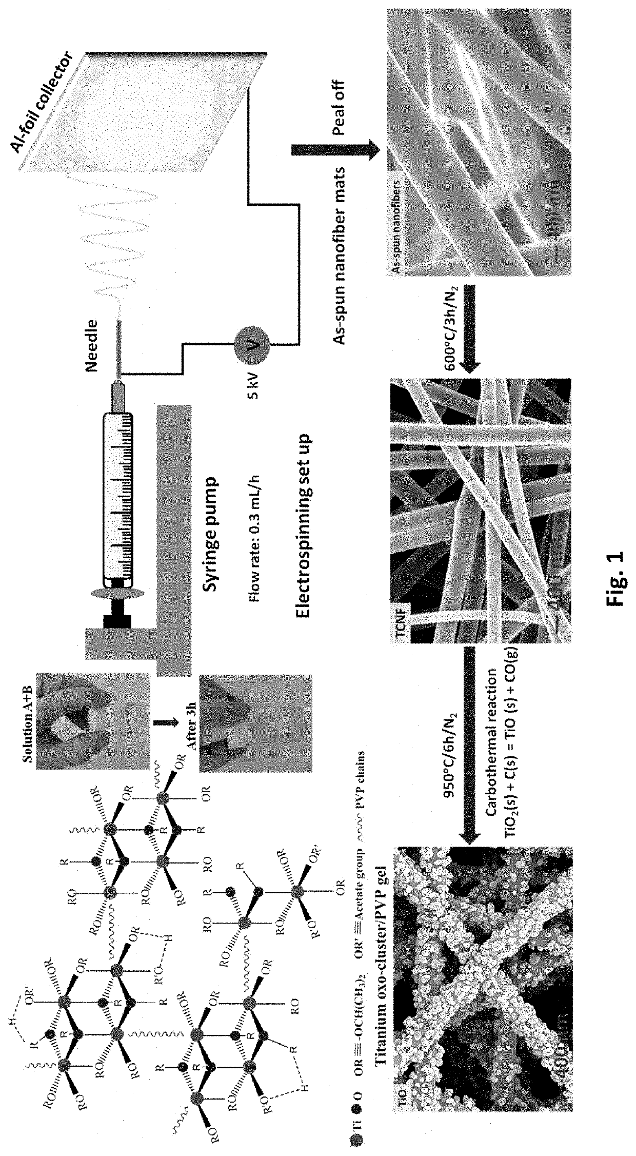
[0123]Electrospinning was used to fabricate free-standing TiO nanofiber mats. First, solution A was prepared by dissolving 0.7 g PVP into 3.75 mL anhydrous ethanol (Alfa Assar) and stirring at room temperature until the solution became transparent. Solution B was made by adding 0.75 mL titanium isopropoxide (TIP) into a mixed solution of 1 mL ethanol and 2 mL glacial acetic acid. Solution B was then added to solution A and stirred at room temperature for 3 h. Due to the Lewis acidity of the Ti4+-centers and Lewis basicity of the alkoxide groups, TiP tends to form oligomers [Ti(OR)4]n, i.e., aggregates (coordination number 6) via alkoxo-bridges. Consequently, ethanol was used as a solvent. The interaction of ethanol (Lewis base) solvent with Ti4+-centers competes against alkoxo-bridge formation and thus minimizes the degree of a...


PUM


Abstract

A nanofiber mat comprises metal oxide nanoparticles distributed on surface of metal oxide nanofibers, wherein the nanofiber mat has a surface area at least 150 m2 / g, and the metal oxide is selected from titanium monoxide TiOx, wherein 0.65<x<1.25, niobium monoxide NbOx, wherein 0.982<x<1.008, vanadium (II) oxide VOx, wherein 0.79<x<1.29, iron (II) oxide FexO, wherein 0.833<x<0.957, manganese (II) oxide MnxO, wherein 0.848<x<1.000, titanium suboxide, TinO2n-1, wherein n>1, molybdenum suboxide, MonO3n-1, wherein n>1, MonO3n-2, wherein n>1, and vanadium suboxide, VnO2n-1, wherein n>1. Cathodes, anodes and batteries are made using the nanofiber mat. Processes for producing the metal oxide nanofiber mat and an electrode including it are also provided.

Description

CROSS REFERENCE TO RELATED APPLICATIONS[0001]This application claims the benefit of U.S. Provisional Application No. 62 / 651,525, filed on, Apr. 2, 2018, the entire disclosure of which is hereby incorporated by reference as if set forth fully herein.STATEMENT OF GOVERNMENT INTEREST[0002]This invention was made with government support under Grant Nos. NSF CBET-1236466 and NSF 1537827 awarded by the U.S. National Science Foundation. The government has certain rights in the invention.FIELD OF THE INVENTION[0003]The present invention relates to electrodes for lithium batteries. In particular, the invention relates to a porous substrate for cathodes for lithium batteries and its production by electrospinning followed by rapidly diffusing sulfur into the porous substrate.BACKGROUND OF THE INVENTION[0004]Since the commercialization of lithium-ion batteries in the early 1990's, electrochemical energy storage demands for portable electronics, electric vehicles, and large-scale storage continu...

Claims


Application Information

Patent Timeline
IPC IPC(8): H01M4/131H01M4/04H01M4/505H01M10/0525H01M4/1391H01M4/02H01M4/139H01M4/48H01M4/62H01M10/054H01M10/052H01M4/13H01M4/38
CPCH01M4/131H01M4/0471H01M4/1391H01M4/505H01M10/0525H01M2004/021H01M4/38H01M2004/028H01M2004/027H01M4/13H01M10/054H01M10/052H01M4/625H01M4/483H01M4/139Y02E60/10
Inventor SINGH, ARVINDERKALRA, VIBHA
Owner DREXEL UNIV
Learn More