Supercharge Your Innovation With Domain-Expert AI Agents!

Biomass gasification device

a gasification device and biomass technology, applied in the direction of gasifier mechanical details, combustible gas purification/modification, combustible gas production, etc., can solve the problems of inability to stabilize power supply, high ash content, difficult to burn, low incineration efficiency, etc., to achieve a wide range of effects, facilitate further decomposition and reforming of tar, and facilitate the effect of reducing tar and soo

Active Publication Date: 2021-07-20
JBEC CO LTD
View PDF24 Cites 0 Cited by
  • Summary
  • Abstract
  • Description
  • Claims
  • Application Information

AI Technical Summary

Benefits of technology

The present invention provides a device that can separately control the temperature of a biomass pyrolytic reactor and a pyrolyzed gas reforming reactor, allowing for optimal pyrolysis and gasification of biomass. This inhibits the formation of harmful byproducts and increases the production of hydrogen-containing gas. The device can also reduce the amount of tar and soot generated during pyrolysis. Additionally, the device can be manufactured at a lower cost and with reduced startup time.

Problems solved by technology

Among renewable energy, the photovoltaic power generation, wind power generation, and tidal power generation are expected to be temporary power supplies, but cannot be stable power supplies because of its unstable generation.
However, since sewage sludge contains nitrogen, phosphorus, potassium and other inorganic substances, as well as soil and the like derived from rainwater, it has high ash content and is difficult to burn.
In addition, since it has a low calorific value, incineration efficiency is low when incineration, which is a disadvantage.
It is known that diphosphorus pentoxide has a high sublimation property and also has a deliquescent property, and thus causes clogging effect in a low-temperature portion of a pipe.
In addition to diphosphorus pentoxide, it is also known that potassium promotes clogging and corrosion of a pipe.
However, in this method, since air is blown into the fluidized bed pyrolysis furnace, the calorific value of the pyrolyzed gas and thus thermal efficiency is reduced.
Therefore, a high output power generation cannot be expected.
Furthermore, the method generates electric power and cannot produce valuable gases such as methane gas and hydrogen gas.
In addition, since the method uses the fluidized bed pyrolysis furnace, generated ash cannot be separated from a flowing medium.
Therefore, sticking of the flowing medium is caused by diphosphorus pentoxide and potassium so that the flowing state becomes unstable.
As a result, the flowing medium has to be frequently replaced, and thus, a problem such as a failure to perform stable continuous operation is assumed.
Therefore, a problem is expected that the flowing state should become unstable due to sticking as in Patent Document 1 of diphosphorus pentoxide and potassium in ash to a flowing medium, for example.
In addition, the pyrolyzed gas reformed in oxygen contains a large amount of carbon monoxide so that it has a low calorific value and rarely contains valuable gases such as methane and hydrogen, which is a problem.
However, also in this method, the pyrolyzed gas contains a large amount of carbon monoxide so that it has a low calorific value and rarely contains valuable gases such as methane and hydrogen, which is a problem.
However, since the preheater, the reforming reactor, and the pyrolytic reactor are vertically arranged in this order from top to bottom, the overall height of the device is significantly increased, which is a problem.
Therefore, the device becomes large-scale.
In addition, even when biomass having a high ash content and a high nitrogen content such as sewage sludge is used as a raw material, this method is expected to inhibit generation of diphosphorus pentoxide while inhibiting generation of N2O in pyrolysis.
In this way of introducing the pyrolyzed gas into the reforming reactor, there was a problem that tar, soot, and the like adhered to an inner wall of the pipe, valves, and the like which the pyrolyzed gas passed through, which caused inevitable clogging troubles.
Thus, there is a concern that the pipe is clogged, the pipe is damaged due to alkali corrosion, and the like.
Therefore, the pyrolyzed coke (char) cannot be combusted when high-ash-content biomass is used as a raw material, which is a disadvantage.
At the same time, the char obtained by pyrolysis of the high-ash-content biomass has even higher ash content due to concentration of ash therein, and thus the char is not suitable for combustion.
Therefore, the aforementioned process itself is difficult to be embodied, which is a disadvantage.

Method used


Image

  • Biomass gasification device
  • Biomass gasification device
  • Biomass gasification device

Examples


example 1

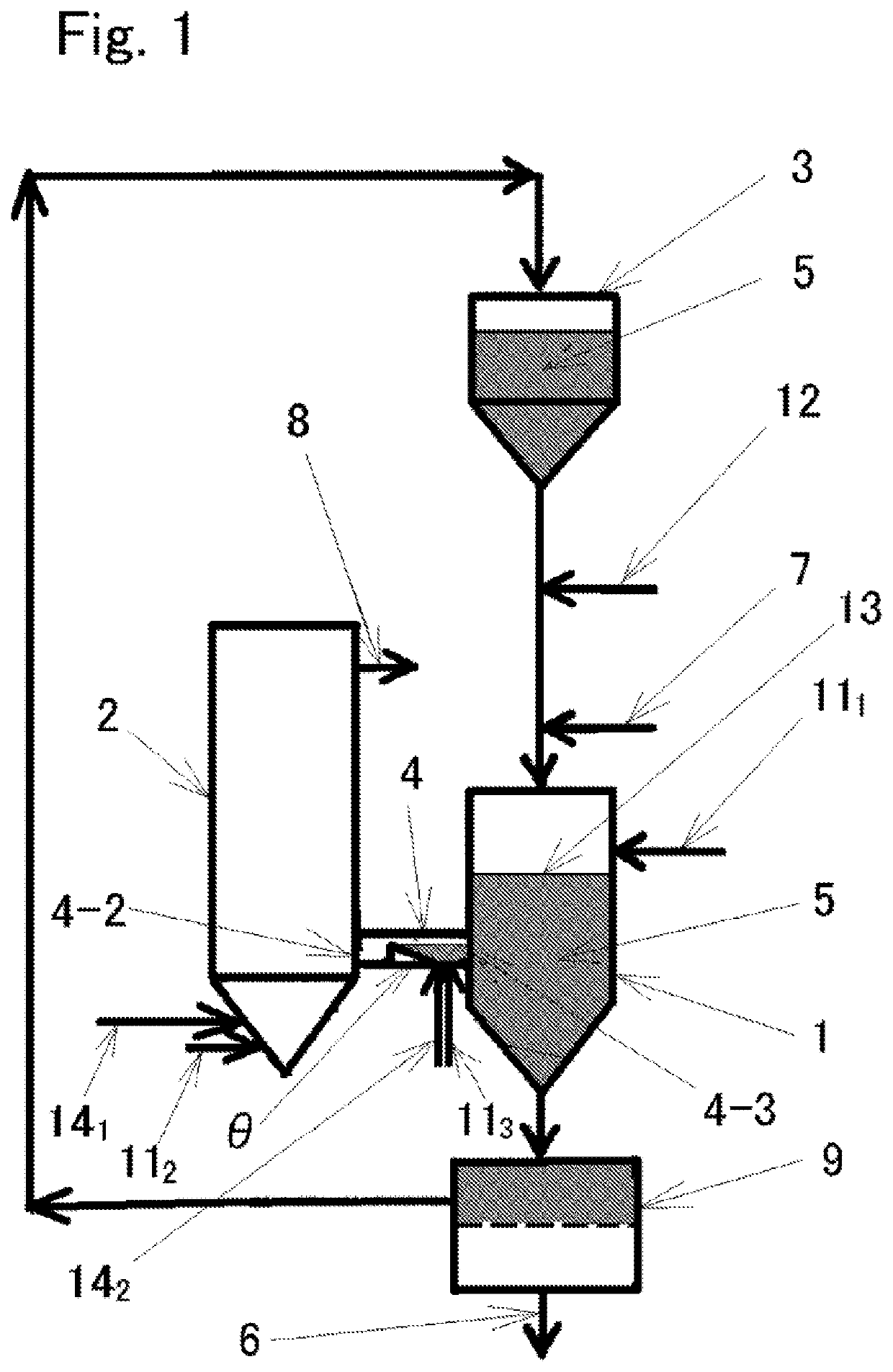
[0150]A biomass raw material, and a gasifying device used for pyrolysis of the biomass raw material and reforming of gas in Example 1 will now be described.

[0151]Sewage sludge was granulated and used as the biomass raw material. The size of the granulated sewage sludge was approximately 6 to 15 mm. Table 1 shows the properties of the sewage sludge. Table 2 shows composition of ash obtained by combusting the sewage sludge.

[0152]

TABLE 1Analysis itemAnalysis valueWater20.0% by massAsh16.0% by massVolatile matter76.7% by massFixed carbon 7.3% by massElemental AnalysisC36.10% by mass H5.98% by massO35.09% by mass N5.26% by massSless than 1.35% by massCLless than 0.22% by massHigher calorific value16.9 MJ / kg

[0153]For each value in Table 1.

[0154]the water content, volatile matter content, and fixed carbon content were measured in accordance with JIS M8812,

[0155]the ash content was measured in accordance with JIS Z 7302-4: 2009, and

[0156]the higher calorific value was measured in accordanc...


PUM

PropertyMeasurementUnit
dry weightaaaaaaaaaa
global warming potentialaaaaaaaaaa
temperatureaaaaaaaaaa

Abstract

The present invention provides a biomass gasification device that optimizes the pyrolysis temperature of biomass, the reforming temperature of pyrolysis gas, and the atmosphere thereof to generate a reformed gas containing a large amount of valuable gas. The present invention related to a biomass gasification device that is provided with a biomass pyrolyzer, a pyrolysis gas reformer, and a pyrolysis gas introduction pipe, wherein: the biomass pyrolyzer is further provided with a heat carrier inlet and outlet ports, and performs pyrolysis on the biomass by heat of the heat carrier; the pyrolysis gas reformer performs steam-reforming on pyrolysis gas generated by the pyrolysis of biomass; the pyrolysis gas reformer is further provided with an air or oxygen blow-in port; and the pyrolysis gas introduction pipe is provided on the biomass pyrolyzer-side surface below the upper surface of the heat carrier layer formed in the biomass pyrolyzer.

Description

TECHNICAL FIELD[0001]The present invention relates to a biomass gasification device, in particular, a biomass gasification device having a biomass pyrolytic reactor for pyrolyzing biomass or preferably biomass having relatively high ash content and a pyrolyzed gas reforming reactor for mixing pyrolyzed gas generated in the biomass pyrolytic reactor with oxygen or air and steam, and partially combusting and reforming the mixed gas.BACKGROUND ART[0002]After the Great East Japan Earthquake on Mar. 11, 2011, renewable energy and distributed energy supply facilities have been reconsidered, and the renewable energy plants using photovoltaic power generation, wind power generation, geothermal power generation, hydroelectric power generation, tidal power generation, and biomass power generation have been focused. In recent years, hydrogen production by water electrolysis using electric power generated with renewable energy has been focused.[0003]Among renewable energy, the photovoltaic powe...

Claims


Application Information

Patent Timeline
Patent Type & Authority Patents(United States)
IPC IPC(8): C10J3/12C10J3/22C10K3/00
CPCC10J3/12C10J3/22C10K3/005C10K3/006C10J2200/09C10J2300/0916C10J2300/0976C10J2300/0993C10J2300/164C10J2300/1246C10B49/18C10B53/02Y02E50/10Y02P20/133
Inventor DOWAKI, NAOKIKAMIUCHI, HISASHIKAMEYAMA, MITSUO
Owner JBEC CO LTD
Features
  • R&D
  • Intellectual Property
  • Life Sciences
  • Materials
  • Tech Scout
  • Unparalleled Data Quality
  • Higher Quality Content
  • 60% Fewer Hallucinations
Learn More