

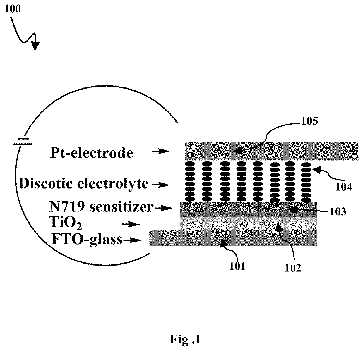
Hybrid ferroelectric discotic liquid crystal solar cell
a liquid crystal solar cell and ferroelectric technology, applied in the field of photovoltaic diodes or solar cells, can solve the problems of ferroelectric solar cells that cannot give pce value more than sq limit, performance of ferroelectric solar cells is less than si solar cells, and performance of ferroelectric or multi-ferrous solar cells is not competitive with si solar cells
- Summary
- Abstract
- Description
- Claims
- Application Information
AI Technical Summary
Benefits of technology
Problems solved by technology
Method used
Image

Examples
Embodiment Construction
[0036]The embodiments herein and the various features and advantageous details thereof are explained more fully with reference to the non-limiting embodiments and detailed in the following description. Descriptions of well-known components and processing techniques are omitted. The examples used herein are intended merely to facilitate an understanding of ways in which the embodiments herein may be practiced and to further enable those of skill in the art to practice the embodiments herein. Accordingly, the examples should not be construed as limiting the scope of the embodiments herein.
[0037]As mentioned above, there is a need to develop a stable ferroelectric or multi ferroelectric solar cell by incorporating an electrolyte composition for attaining improved power conversion efficiency and thereby overcoming SQ limitation. The embodiments herein achieve this by providing a stable hybrid ferroelectric discotic liquid crystal solar cell by incorporating an electrolyte composition. R...
PUM
| Property | Measurement | Unit |
|---|---|---|
| thickness | aaaaa | aaaaa |
| particle size | aaaaa | aaaaa |
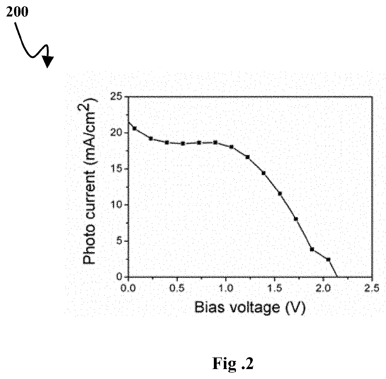
| short circuit photocurrent | aaaaa | aaaaa |
Abstract
Description
Claims
Application Information