Method of and apparatus for manufacturing the metallic iron

a technology of metallic iron and manufacturing method, which is applied in the direction of manufacturing converters, furnace types, furnaces, etc., can solve the problems of reducing the purity of metallic iron (iron quality), increasing the amount of slag, and lowering the yield of refined molten iron

Inactive Publication Date: 2002-01-17
KOBE STEEL LTD
View PDF0 Cites 27 Cited by
  • Summary
  • Abstract
  • Description
  • Claims
  • Application Information

AI Technical Summary

Benefits of technology

[0014] Further, according to the method of this invention, the compact may be reduced and melted by charging the compact above the fire grate disposed in the inside of a furnace used as the packed bed, and burning the fuel below the fire grate or providing a layerd bed comprising refractory material or a lumpy carbonaceous material having open cells when layered bed may be disposed on the fire grate. Further, it is desirable to supply an oxygen-containing gas from a gas supply port above the fire grate to burn the gases generated from the compact in order to increase the heat efficiency by the effect of utilizing the reducing gas. It is also preferred to mix an auxiliary fuel to the oxygen-containing gas. Further, it is also effective to supply an auxiliary fuel toward the space below the fire grate in order to enhance the effect according to this invention.
[0019] The present inventors have made earnest studies for dissolving the foregoing subject and have found that reduced iron at high Fe purity with less inclusion of the slag components can be produced by using less amount of the carbonaceous reducing agent and less fuel consumption, and loss of refractories can be suppressed, by charging a compact at least comprising a carbonaceous reducing agent and an iron oxide containing material (hereinafter sometimes referred to simply as "compact") in a packed bed, burning the fuel sufficiently below the fire grate, heating and reducing of the iron oxide contained in the compact to more than 90% while keeping the compact in a solid state, and then melting the same.

Problems solved by technology

However, since the reduced iron obtained by the conventional reduced iron production method includes a great amount of slag componentscomponents such as SiO.sub.2, Al.sub.2O.sub.3 and CaO contained in the iron oxide used as the raw material (gangue elements in iron ores) or carbon material (ash in coals), there are a problem that the purity of the metallic iron (iron quality) is lowered.
While the slag components can be separated and removed by the following refining step, the increase in the amount of slags not only lowers the yield of the refined molten iron but also gives undesired effects on the operation cost of the electric arc furnace, so that reduced iron of high quality and with less content of the slag has been demanded.
However, iron ores of high iron quality have to be used as the raw material for the manufacture of reduced iron in the existent reduced iron manufacturing method, which greatly narrows the range for the selection of practical iron making materials.
Further, it is a final purpose to obtain reduced solid products as intermediate products in the existent method as described above and this requires additional steps of transportation, storage, briquetting or cooling till they are sent to the following step of refining, to result in problems that large energy loss is caused or the energy and the special apparatus are required for briquetting.
However, since this method requires two steps of preliminary reduction and final reduction in the molten iron bath, it involves a problem not only of troublesome operations but also of remarkable loss of refractories since the molten iron oxides (FeO) present in the molten bath are in direct contact with refractories.
However, although the metallic iron at high purity can be obtained in this method, it requires a large scale facility and it is difficult to save spacing for the facility.

Method used


Image

  • Method of and apparatus for manufacturing the metallic iron
  • Method of and apparatus for manufacturing the metallic iron
  • Method of and apparatus for manufacturing the metallic iron

Examples


example 1

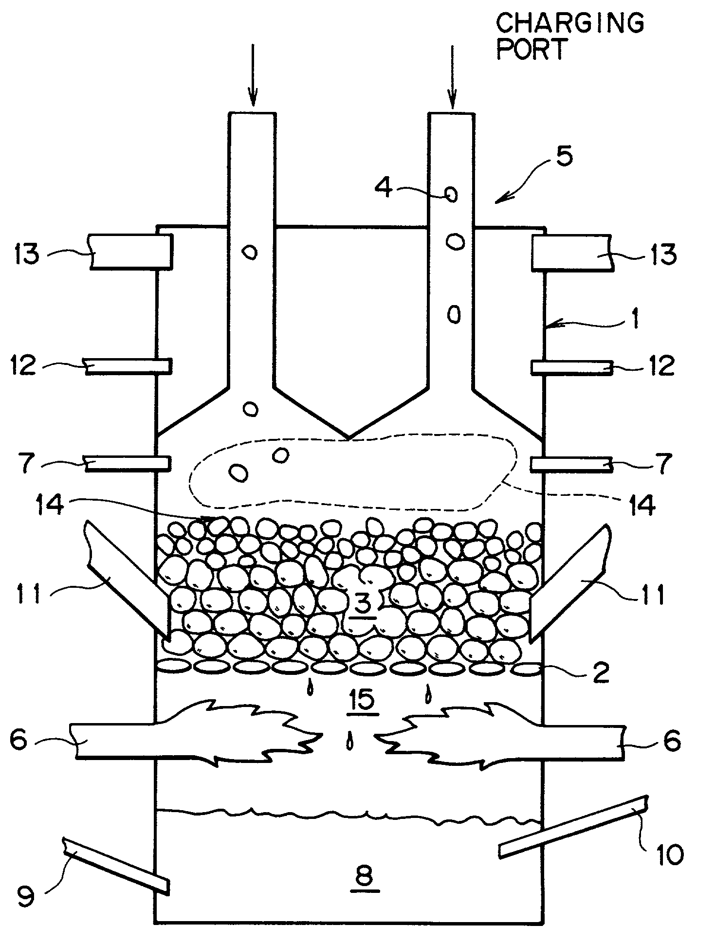
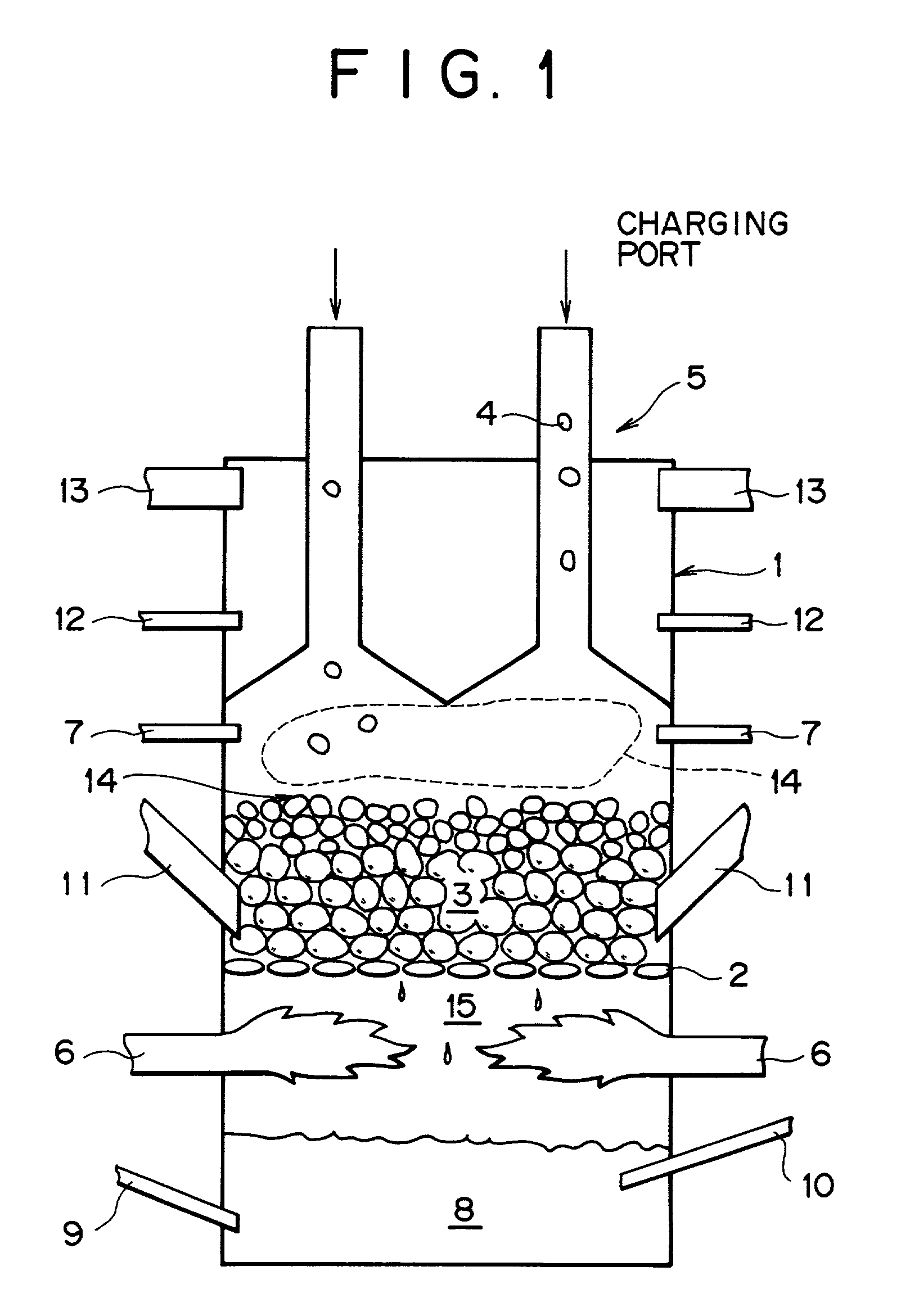
[0067] The following experiment was conducted by using a packed bed shown in FIG. 1. A water cooled fire grate (2) as a water-cooled rostor is disposed in a furnace body (1) of 60 cm inner diameter.times.2 m height, refractories comprising alumina (average particle size: 15 mm) were charged on the fire grate through a refractory charging mechanism (11) and, subsequently, the refractories are appropriately supplemented to keep the thickness of the refractory layer to 20 cm and heated by the heat of combustion formed in the lower portion of the furnace. Iron ore powder, coal powder and binder (each of 75 .mu.m or less in average grain size) of the following chemical composition, which were uniformly mixed at the following ratio and then formed into pellets (spheres), were supplied on the refractories through a compact charging mechanism (5) (charged height: 5-40 cm). A fuel (natural gas) mixed with air was introduced in a fuel combustion space below the fire grate (2) through a fuel s...

example 2

[0078] FIG. 3 shows the relation between the reduction degree of the compact and the temperature of the compact in Example 1. It can be seen from FIG. 3 that the temperature of the compact is from 1000.degree. C. to 1200.degree. C. for the reduction degree of the iron oxide of about from 20% to 85%. In view of the above, it can be seen that even when heat of combustion at high temperature is supplied to the compact, this is consumed by the endothermic reaction, and the temperature of the compact is kept constant and the reaction scheme shown below is established.

[0079] Fe.sub.2O.sub.3+3CO=2Fe+3CO.sub.2

[0080] CO.sub.2+C=2CO

[0081] In the graph, are shown the temperature Ts for the compact and the reduction degree RD for the compact.

example 3

[0082] An experiment was conducted in the same manner as in Example 1 except for changing the atmospheric temperature in the furnace (operation temperature) for 1300.degree. C., 1350.degree. C., 1400.degree. C. and 1450.degree. C. and behavior of the compact was measured. In this experiment, oxygen potential in the compact of 20 to 25 mm diameter was measured by using a needle type oxygen sensor. FIG. 4 shows for a relationship between the temperature and the oxygen potential in the compact on a Fe--O phase diagram.

[0083] As can be seen from FIG. 4, the compact was melted and dripped when the atmospheric temperature in the furnace was 1350.degree. C. or higher but the compact was not melted and dripped when the atmospheric temperature in the furnace was at 1300.degree. C. It can be seen that the compact was melted and dripped when the measured curve remained within the liquid phase existent region (L).


PUM

PropertyMeasurementUnit
temperatureaaaaaaaaaa

Abstract

A method of manufacturing reduced iron at high Fe purity efficiently with less intrusion of a slag components using less carbonaceous reducing agent and fuel, comprising charging a compact of the iron oxide containing a carbonaceous reducing agent in a packed bed, reducing the iron oxide to 90% or more while keeping in a solid state by a heat source formed from the lower portion of the furnace and then melting the same, as well as an apparatus for manufacturing the metallic iron, comprising a fire grate disposed in the inside of a packed bed, a compact charged layer on the fire grate, a charging product charging mechanism for supplying the compact and a mechanism for discharging an exhaust gas in the furnace, and a fuel charging mechanism, a fuel combustion space and a molten product stores bath disposed below the fire grate.

Description

[0001] 1. Field of the Invention[0002] This invention concerns a technique of heating iron oxide containing materials such as iron ores together with carbonaceous reducing agents such as carbon materials and reducing and melting them to obtain metallic iron and, more specifically, it relates to a method of and an apparatus for manufacturing the metallic iron at high purity by separating a slag components intruded as a gangue mineral in iron oxide sources by using a packed bed.[0003] 2. Statement of Related Art[0004] As a direct reduction method of directly reducing the iron oxides such as iron ores or iron oxide pellets by a carbon source such as a carbon material or a reducing gas, a packed bed method represented by a Midrex process has been known so far. The direct reduction method of this type is a method of blowing a reducing gas reformed, for example, from natural gases through bustle ports charging mechanism at a lower portion of a packed bed and reducing iron oxides by utiliz...

Claims


Application Information

Patent Timeline
Patent Type & Authority Applications(United States)
IPC IPC(8): C21B11/02C21B13/00C21B13/02C22B1/16C21C5/28C22B5/10
CPCC21B11/02C21B13/0046Y02P10/134C21B13/0053
Inventor NAGATA, KAZUHIROKOBAYASHI, ISAONEGAMI, TAKUYAURAGAMI, AKIRATANIGAKI, YASUHIROTOKUDA, KOJIKIKUCHI, SHOICHI
Owner KOBE STEEL LTD
Why Eureka
Try Eureka