Aluminum target material for sputtering and method for producing same

a technology of sputtering and target material, which is applied in the direction of vacuum evaporation coating, electrolysis components, coatings, etc., can solve the problems of defective thin films, poor heat resistance, and low resistance of high melting metals such as cr, ta, ti, etc., and achieves the effect of small splashing and low resistan

Inactive Publication Date: 2002-02-07
HITACHI METALS LTD
View PDF0 Cites 56 Cited by
  • Summary
  • Abstract
  • Description
  • Claims
  • Application Information

AI Technical Summary

Benefits of technology

0022] Accordingly, an object of the present invention is to provide an Al-based target material for sputtering containing finely divided intermetallic compounds and having a microstructur

Problems solved by technology

However, the thin films of the high melting metals such as Cr, Ta, Ti, etc. do not meet this requirement due to their high resistivity.
However, during the sputtering process of such a combined target material, dust particles generate from the seams between the target pieces to result in defective thin films.
Since a thin film of pure Al has a low resistivity, but a poor heat resistance, during such a heat treatment, minutes protrusions, called hillocks, are formed on the surface.
The hillock formation causes several problems such as a short circuit in Al thin-film interconnections and thin-film electrodes, and a corrosion of the Al thin-film interconnections and thin-film electrodes due to etching solutions penetrated through the holes made in an insulating layer, a protective layer, etc. due to hillock growth.
However, the microscopic segregation in the cast ingot cannot be avoided because flaky intermetallic compounds therein aggregate together.
Therefore, a target material made by a casting method is not suitable for forming thin films serving as fine interconnections of LCD.
However, handling of fine Al powder and fine powders of the additive el

Method used


Image

  • Aluminum target material for sputtering and method for producing same
  • Aluminum target material for sputtering and method for producing same
  • Aluminum target material for sputtering and method for producing same

Examples


examples 1-10

[0092] Each Al alloy having a composition shown in Table 1 was gas-atomized in nitrogen atmosphere and classified into a powder having a maximum particle size of 60 .mu.m. The powder was charged into a soft iron can of 133 mm in inner diameter, 15 mm in height and 2 mm in thickness. The can was degassed under heating while evacuating the can to a pressure of 10.sup.-3 Pa or lower. Then, the powder was pressure-sintered by HIP (hot isostatic press) under a pressure of 127 MPa at 550.degree. C. for 3 hours. Then the soft iron can was removed by machining to obtain each sintered, non-rolled, single-phase target material of 100 mm in diameter and 4 mm in thickness.

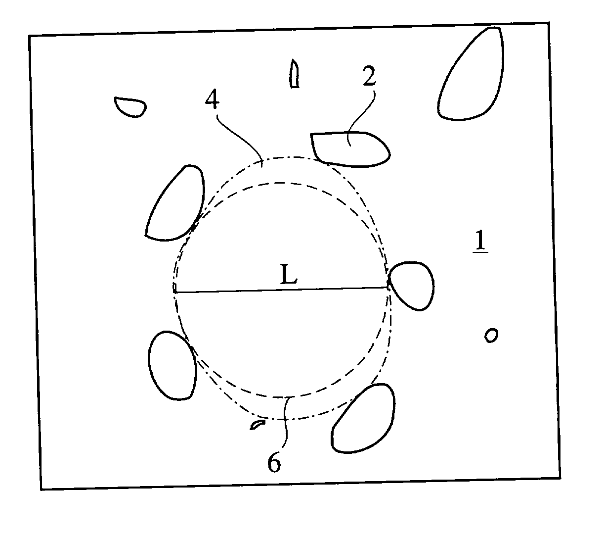
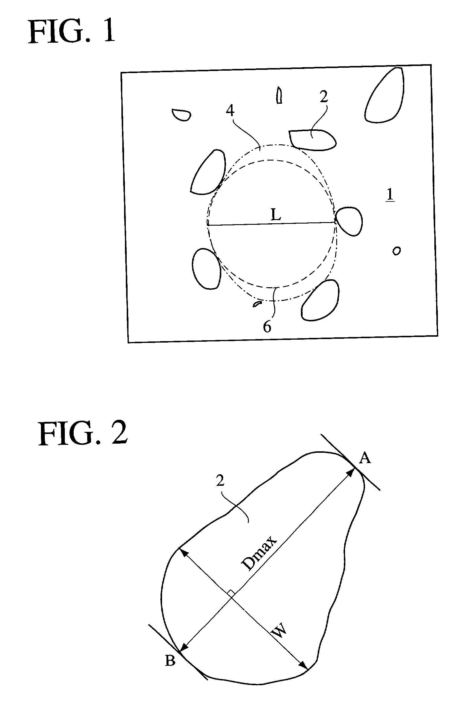
[0093] The microstructure of each target material thus obtained was observed under an optical microscope (.times.400) to measure the maximum diameter and the maximum aspect ratio (maximum value of longer diameter / shorter diameter) of the intermetallic compound in the microstructure, and the diameter of the largest inscribed ci...

examples 11-20

[0098] Each Al alloy having a composition shown in Table 2 was made into a rapid solidification powder by a gas atomizing method in nitrogen atmosphere and classified into a powder having a maximum particle size of 60 .mu.m. The powder was charged into a soft iron can having an internal volume of 330 mm.times.530 mm.times.50 mm and a thickness of 2 mm. The can was degassed under heating while evacuating the can to a pressure of 10.sup.-3 Pa or lower. The powder was subjected to HIP under a pressure of 127 MPa at 550.degree. C. for 3 hours, and then hot-rolling at a temperature and a rolling reduction shown in Table 2. Then the soft iron can was removed by machining to obtain each sintered, rolled, single-phase target material having a size of 550 mm.times.690 mm.times.6 mm.

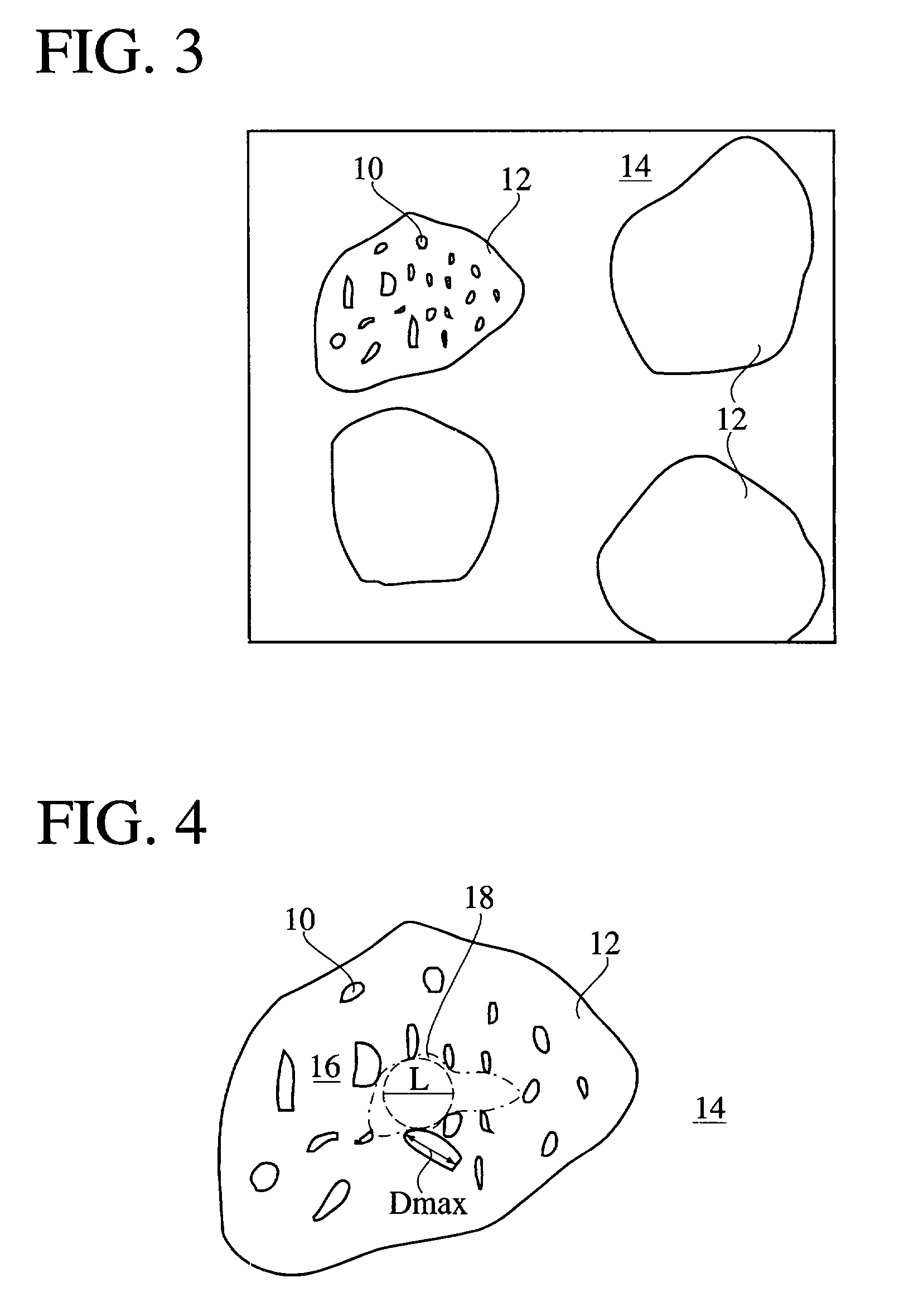
[0099] The maximum diameter and the maximum aspect ratio of the intermetallic compound in the microstructure of the target material, the diameter of the largest inscribed circle in the pure Al area, and the number...

examples 21-25

[0107] Each Al alloy having a composition shown in Table 3 and a pure Al were made into rapid solidification powders by a gas atomizing method in nitrogen atmosphere and classified into a respective powder having a particle size of 150 .mu.m or less. The Al alloy powder and the pure Al powder thus obtained were blended in a rocking mixer so as to have a final composition of the target material as shown in Table 3. The powder mixture was charged into a soft iron can having an internal volume of 133 mm (inner diameter).times.10 mm and a thickness of 2 mm. After degassing the can at 400.degree. C. for 3 hours while evacuating the can to a pressure of 10.sup.-3 Pa or lower, the can was sealed. Then, the powder was subjected to HIP under a pressure of 127 MPa for 3 hours at a temperature shown in Table 3. After removing the can, the sintered powder was machined into a disc shape of 100 mm (diameter).times.4 mm to obtain each sintered, non-rolled, composite-phase target material having a ...


PUM

PropertyMeasurementUnit
Temperatureaaaaaaaaaa
Lengthaaaaaaaaaa
Angleaaaaaaaaaa

Abstract

The first Al-based target material for sputtering contains 0.01-10 atomic % of at least one intermetallic compound-forming element, and an intermetallic compound having a maximum diameter of substantially 50 mum or less. The second Al-based target material for sputtering has a microstructure comprising an alloy phase containing 20 atomic % or less of the intermetallic compound-forming element and Al and an Al matrix phase comprising substantially pure Al, the maximum diameter of the intermetallic compound in the alloy phase being substantially 50 mum or less. The content of the intermetallic compound forming element based on the whole structure is 0.01-10 atomic %. These target materials are produced by pressure-sintering a rapid solidification powder at 400-600° C. After the pressure sintering, the target material is preferably hot-rolled at 400-600° C.

Description

[0001] The present invention relates to an aluminum-based target material for sputtering used in forming thin-film electrodes, thin-film interconnections, etc. for a liquid crystal display (hereinafter referred to as LCD), and a production method thereof.DESCRIPTION OF THE RELATED ART[0002] Thin films of a high melting metal such as Cr, Ta, Ti, etc. or its alloy have been conventionally used as interconnections, electrodes, etc. of LCD, thin-film sensor, etc. comprising a glass substrate and thin-film devices formed thereon. Recent demands for LCD of larger size and higher resolution require to reduce the resistivity, relieve the stress and stabilize the characteristics of the thin-film interconnections and electrodes to avoid the delay of signals.[0003] For example, a specific resistivity of 15 .mu..OMEGA..multidot.cm or less is required for the electrode used in a large color LCD of 12-inch large or more. However, the thin films of the high melting metals such as Cr, Ta, Ti, etc. ...

Claims


Application Information

Patent Timeline
IPC IPC(8): C22C21/00C23C14/34
CPCC22C21/00C23C14/3414
Inventor TAKASHIMA, HIROSHI
Owner HITACHI METALS LTD
Why Eureka
Try Eureka