

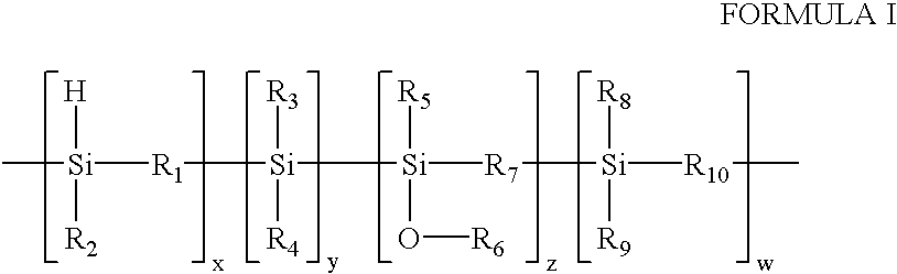
Low dielectric constant polyorganosilicon materials generated from polycarbosilanes
a technology of polycarbosilane and low dielectric constant, which is applied in the direction of transportation and packaging, coating, layered products, etc., can solve the problems of increasing the rc time constant, increasing the power consumption of the ic, and reducing the signal propagation speed
- Summary
- Abstract
- Description
- Claims
- Application Information
AI Technical Summary
Problems solved by technology
Method used
Image


Examples
example 2
[0095] Two grams of allylhydridopolycarbosilane (AHPCS) purchased from Starfire Systems, Inc. was dissolved in 4 grams of anhydrous dibutyl ether. The solution was then filtered through a 0.2 micron filter. About 2 mL of this solution was dispensed onto the surface of 4" wafer and then the wafer was spun at 2000 rpm for 30 seconds. The coated wafer was heated at sequentially elevated temperatures of 80C, 150C, and 220C for three minutes each under atmosphere (air) conditions. Then the film was cured in a furnace at 400.degree. C. for 60 minutes under a nitrogen blanket environment.
[0096] FIG. 3 represents the infrared spectra of the films after each process step. (a) as spun; (b) baked at 80.degree. C.; (c) baked at 150.degree. C.; (d) baked at 250.degree. C.; and (e) cured at 400.degree. C. IR spectra were obtained from the film as-spun and after each process step. The assignment of the infrared absorption of this material is shown in Table 1. The structural change of the spun film...
example 3
[0097] Two grams of hydridopolycarbosilane (HPCS), [SiH.sub.2CH.sub.2].sub-.n, purchased from Starfire Systems, Inc. was dissolved in 4 grams of anhydrous dibutyl ether. The solution was then filtered through a 0.2 micron filter. About 2 mL of this solution was dispensed onto the surface of a 4" wafer and then the wafer was spun at 2500 rpm for 30 seconds. As in the earlier Examples, the coated wafer was heated sequentially at 80C, 150C, and 220C for three minutes, each step carried out under atmosphere (air) conditions. Then the film was cured in a furnace at 400.degree. C. for 60 minutes under a Nitrogen blanket environment.
[0098] FIG. 4 represents the infrared spectra of the films after each process step. (a) as spun; (b) baked at 80.degree. C.; (c) baked at 150.degree. C.; (d) baked at 250.degree. C.; and (e) cured at 400.degree. C. IR spectra were obtained for the films as-spun and after each process step. The assignment of the infrared absorption of this material is shown in T...
example 4
[0100] Two grams of allylhydridopolycarbosilane (AHPCS) purchased from Starfire Systems, Inc. was dissolved in 4 grams of anhydrous dibutyl ether. The solution was then filtered through a 0.2 micron filter. About 2 mL of this solution was dispensed onto the surface of a 4" wafer and then the wafer was spun at 2000 rpm for 30 seconds. The coated wafer was heated sequentially at 80C, 150C, and 250C for three minutes each under atmospheric (air) conditions. Then the film was cured in a furnace at 400.degree. C. for 30 minutes under a nitrogen blanket environment.
[0101] The refractive index was measured on a Woolam ellipsometer. The film after cure at 400.degree. C. showed film thickness of 5466 A and refractive index of 1.479 at 633 nm. The dielectric constant was measured by the standard CV curve technique, using MOS capacitor structure. The dielectric constant of the prepared films was 2.4. The peak area for cured films: Si--H: 7.09, C--H 1.53.
PUM
| Property | Measurement | Unit |
|---|---|---|
| Length | aaaaa | aaaaa |
| Angle | aaaaa | aaaaa |
| Angle | aaaaa | aaaaa |
Abstract
Description
Claims
Application Information