[0017] The addition of elements of comparatively
low density relative to
rhodium, such as, for example, aluminum and
chromium, maintains the overall density of the alloy of the present invention to levels below those of many
refractory superalloys. In some embodiments, the alloy of the present invention has a density of less than about 11 g / cc, and in particular embodiments, the present alloy has a density of less than about 10 g / cc. In certain embodiments, the alloy of the present invention comprises aluminum, in an amount
ranging from about 8 atomic percent to about 20 atomic percent;
chromium, in an amount
ranging from about 10 atomic percent to about 30 atomic percent; and the balance comprises
rhodium, wherein the rhodium is present in an amount of at least about 16 atomic percent. Maintaining the Rh content at a level of at least about 16 atomic percent allows the alloy of the present invention to take
advantage of the excellent performance of Rh at high temperatures, such as, for example, the
oxidation resistance of Rh. In particular embodiments, the present alloy comprises aluminum in an amount
ranging from about 12 atomic percent to about 16 atomic percent. Maintaining Al and Cr at these levels allows thin,
protective oxide scale formation when the alloy is exposed to high temperatures, which enhances the ability of the alloy to
resist further oxidation.
[0019] Some embodiments of the present invention provide for the addition of further alloying elements. In some embodiments, the alloy of the present invention further comprises up to about 45 atomic percent
nickel (Ni), up to about 17 atomic percent
ruthenium (Ru), up to about 1.5 atomic percent
zirconium (Zr), up to about 20 atomic percent
palladium (Pd), and up to about 20 atomic percent
platinum (Pt). With the exception of Zr, each of these elements performs as a lower cost, lower density substitute for Rh. Replacing Rh with such alternative elements, however, generally results in a compromise in performance. For example, the substitution of Ni for Rh results in a decrease in alloy strength,
oxidation resistance, and
melting point. The amount of Ni added to the alloy of the present invention is generally controlled to be within a certain range in order to maintain the desired performance level. In particular embodiments, the alloy of the present invention comprises
nickel, in an amount ranging from about 20 atomic percent to about 44 atomic percent, up to about 12 atomic percent
ruthenium, up to about 1 atomic percent
zirconium, up to about 18 atomic percent
palladium, and up to about 10 atomic percent
platinum. The addition of
zirconium achieves a certain amount of
solid solution strengthening, wherein the zirconium remains dissolved in the FCC phase and hardens the FCC phase by straining the surrounding FCC
crystal structure. Additionally, as an alloy of the present invention comprising zirconium is exposed to air under high-temperature service conditions or during a heat treatment in air, the zirconium oxidizes to form a uniform dispersion of very small, very hard
oxide particles that reinforces the FCC phase and provides significant high temperature strength.
[0020] To further capitalize upon the benefits described above, certain embodiments of the present invention provide an alloy comprising about 15 atomic percent aluminum; chromium, in an amount ranging from about 12 atomic percent to about 16 atomic percent; up to about 12 atomic percent
ruthenium; about 1 atomic percent zirconium; and the balance comprising rhodium, wherein the rhodium is present in an amount of at least about 16 atomic percent; wherein a
microstructure of the alloy comprises a face-centered-cubic phase and a B2-structured phase, wherein the B2-structured phase is present in the
microstructure in an amount ranging from about 20
volume percent to about 35
volume percent, and wherein the microstructure is essentially free of an L1.sub.2-structured phase at temperatures greater than about 1000.degree. C. Alternative embodiments provide an alloy comprising about 15 atomic percent aluminum; chromium, in an amount ranging from about 18 atomic percent to about 24 atomic percent; nickel, in an amount ranging between about 22 atomic percent and about 30 atomic percent; ruthenium, in an amount ranging between about 8 atomic percent and about 17 atomic percent; and the balance comprising rhodium, wherein the rhodium is present in an amount of at least about 16 atomic percent; wherein a microstructure of the alloy comprises a face-centered-cubic phase and a B2-structured phase, wherein the B2-structured phase is present in the microstructure in an amount ranging from about 20
volume percent to about 35 volume percent, and wherein the microstructure is essentially free of an L1.sub.2-structured phase at temperatures greater than about 1000.degree. C. Other embodiments provide an alloy comprising about 15 atomic percent aluminum; chromium, in an amount ranging from about 18 atomic percent to about 28 atomic percent; nickel, in an amount ranging between about 30 atomic percent and about 45 atomic percent; ruthenium, in an amount ranging between about 6 atomic percent and about 10 atomic percent and the balance comprising rhodium, wherein the rhodium is present in an amount of at least about 16 atomic percent; wherein a microstructure of the alloy comprises a face-centered-cubic phase and a B2-structured phase, wherein the B2-structured phase is present in the microstructure in an amount ranging from about 20 volume percent to about 35 volume percent, and wherein the microstructure is essentially free of an L1.sub.2-structured phase at temperatures greater than about 1000.degree. C. Alloys of the present invention with compositions in keeping with the above ranges have shown desirable levels of performance with respect to such properties as, for example, oxidation resistance, strength, and density.
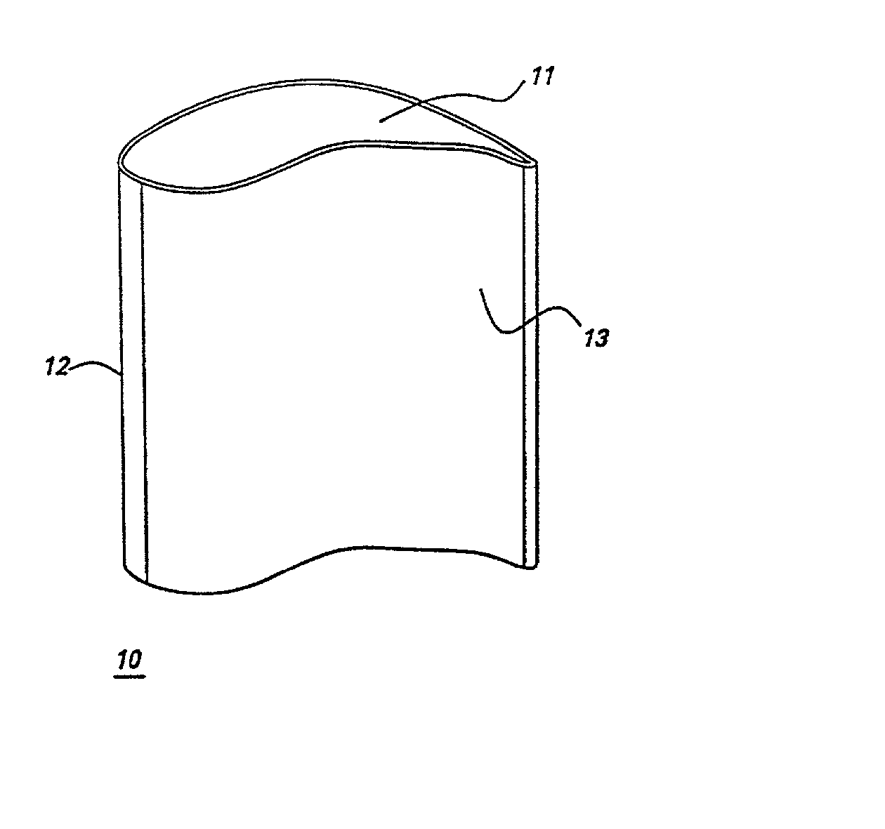
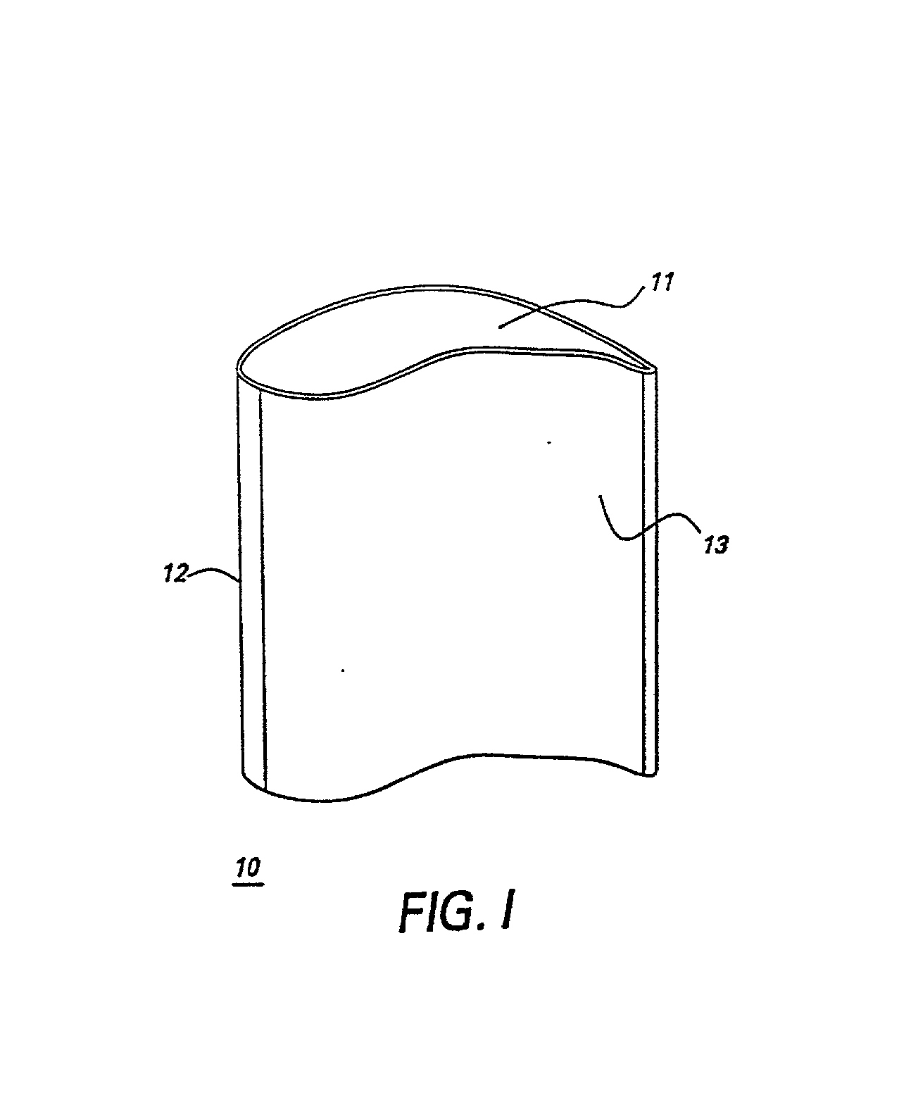
[0023] In some embodiments, the gas turbine engine component is a blade of an aircraft engine, a vane of an aircraft engine, a bucket of a power generation turbine engine, or a
nozzle of a power generation turbine. Referring to FIG. 1, in particular embodiments the gas turbine engine component comprises an airfoil 10, and the airfoil comprises the alloy. Specific embodiments provide that the airfoil 10 comprises a tip section 11, a
leading edge section 12, and a
trailing edge section 13, and wherein at least one of said tip section 11, said
leading edge section 12, and said
trailing edge section 13 comprises said alloy. Having only particular sections (i.e., those sections known to experience the most aggressive stress-temperature combinations) of the airfoil comprise the alloy of the present invention minimizes certain drawbacks of alloys comprising significant amounts of, for example, rhodium,
platinum, or
palladium, including their high cost and
high density in comparison to conventional airfoil materials. These drawbacks have a reduced effect on the overall component because the comparatively expensive and dense alloy of the present invention comprises only a fraction of the overall surface area of the component. The properties of the component are thus "tailored" to the expected localized environments, reducing the need for compromise during the
design process and increasing the expected operating lifetimes for new and repaired components.

