
Metal alloys for the reflective or the semi-reflective layer of an optical storage medium

a technology of optical storage medium and reflective layer, which is applied in the direction of photomechanical equipment, instruments, transportation and packaging, etc., can solve the problems of reducing the reducing the service life of the disc, so as to achieve the effect of high reflectivity, similar sputtering characteristics, and corrosion resistan

Inactive Publication Date: 2003-07-24
TARGET TECH
View PDF31 Cites 33 Cited by
  • Summary
  • Abstract
  • Description
  • Claims
  • Application Information

AI Technical Summary

Benefits of technology

[0024] It is another objective of this invention to create a new class of copper containing alloys for thin film reflective layers with moderate to high reflectivity and good corrosion resistance.
[0025] It is another objective of this invention to provide a lower cost alternative to the gold reflective layer in a recordable compact disc and still satisfy other functional requirements of the disc such as high reflectivity and corrosion resistance.
[0026] It is a further objective of this invention to provide a silver-based or a copper-based alloy for the semi-reflective version of the prerecorded mini-disc (MD) and other current or future generations of optical discs in which reflectivity, corrosion resistance, and ease of application are all important requirements for a low cost and high performance product.III.

Problems solved by technology

Although gold naturally offers a rich color and satisfies all the functional requirements of a highly reflective layer, it is comparatively much more expensive than aluminum.
But unfortunately, the exchange is not truly satisfactory because the copper alloy's corrosion resistance, in general, is considered worse than aluminum, which results in a disc that has a shorter life span than one with an aluminum reflective layer.
But because the dye may contain halogen ions or other chemicals that can corrode the reflective layer, many commonly used reflective layer materials such as aluminum may not be suitable to give the CD-R disc a reasonable life span.
But while gold satisfies all the functional requirements of CD-R discs, it is a very expensive solution.
But once again, it is also comparatively more expensive than other metals.
Moreover, silicon also has a tendency to react with oxygen and nitrogen during sputtering, which introduces a whole additional set of problems.
For example, usually the application of silicon requires a more complicated sputtering apparatus than one that is normally required to apply other reflective metals.
And as a result, neither gold nor silicon offers an ideal semi-reflective layer for use in this type of disc.

Method used


Image

  • Metal alloys for the reflective or the semi-reflective layer of an optical storage medium
  • Metal alloys for the reflective or the semi-reflective layer of an optical storage medium
  • Metal alloys for the reflective or the semi-reflective layer of an optical storage medium

Examples


second embodiment

[0054] In a second embodiment, the copper is alloyed with a comparatively small amount of cadmium, which is an oxide former and an oxygen scavenger that will improve the oxidation resistance of copper while having a low impact on reflectivity. In this embodiment, the relationship between the amount of cadmium and copper ranges from about 0.01 a / o percent (atomic percent) to about 15 a / o percent cadmium and from about 85 a / o percent to about 99.99 a / o percent copper.

[0055] The solubility limits of cadmium in copper at 500.degree. C. and 300.degree. C. are respectively about 1.40 and 0.50 a / o percent. And at the eutectic temperature of copper and cadmium, the maximum solubility of cadmium in copper is approximately 2.14 a / o percent. Thus, for the same reasons as for the copper-silver alloys, it is again desirable to keep the cadmium in a solid solution of copper for use as a sputtering target (an example of which is item 400 shown in FIGS. 7 and 8). As a result, it is another embodime...

third embodiment

[0056] In a third embodiment, the copper is alloyed with a comparatively small amount of gold. Gold is a noble metal, and will increase the corrosion resistance of copper. Gold is isomorphous with copper and can be added in any proportion to copper and still keep the copper-gold alloy a single phase; thus gold's addition to copper as an alloying element is theoretically unlimited and only limited in practice by the ultimate cost of the alloy. In this embodiment, the relationship between the amount of gold and copper ranges from about 0.01 a / o percent (atomic percent) to about 30 a / o percent gold, and from about 70 a / o percent to about 99.99 a / o percent copper. But preferably, in respect to each metal, this alloy has from about 0.1 a / o percent to about 5.0 a / o percent gold and from 95 a / o percent to about 99.9 a / o percent copper.

fourth embodiment

[0057] In a fourth embodiment, the copper is alloyed with a comparatively small amount of magnesium. In this embodiment, the relationship between the amount of magnesium and copper ranges from about 0.01 a / o percent (atomic percent) to about 10 a / o percent magnesium and from about 90 a / o percent to about 99.99 a / o-percent copper. But preferably, in respect to each metal, this alloy has from about 0.10 a / o percent to about 5.0 a / o percent magnesium and from about 95 a / o percent to about 99.1 a / o percent copper. Similar to cadmium, magnesium is also a strong oxide former and oxygen scavenger, and is, therefore, capable of reacting with any residual oxygen in copper to form magnesium oxide.


PUM

PropertyMeasurementUnit
thickaaaaaaaaaa
distanceaaaaaaaaaa
lengthaaaaaaaaaa

Abstract

A silver-based alloy thin film is provided for the highly reflective or semi-reflective layer of optical discs. Alloy additions to silver include gold, palladium, copper, rhodium, ruthenium, osmium, iridium, and platinum. These alloys have moderate to high reflectivity and reasonable corrosion resistance in the ambient environment.

Description

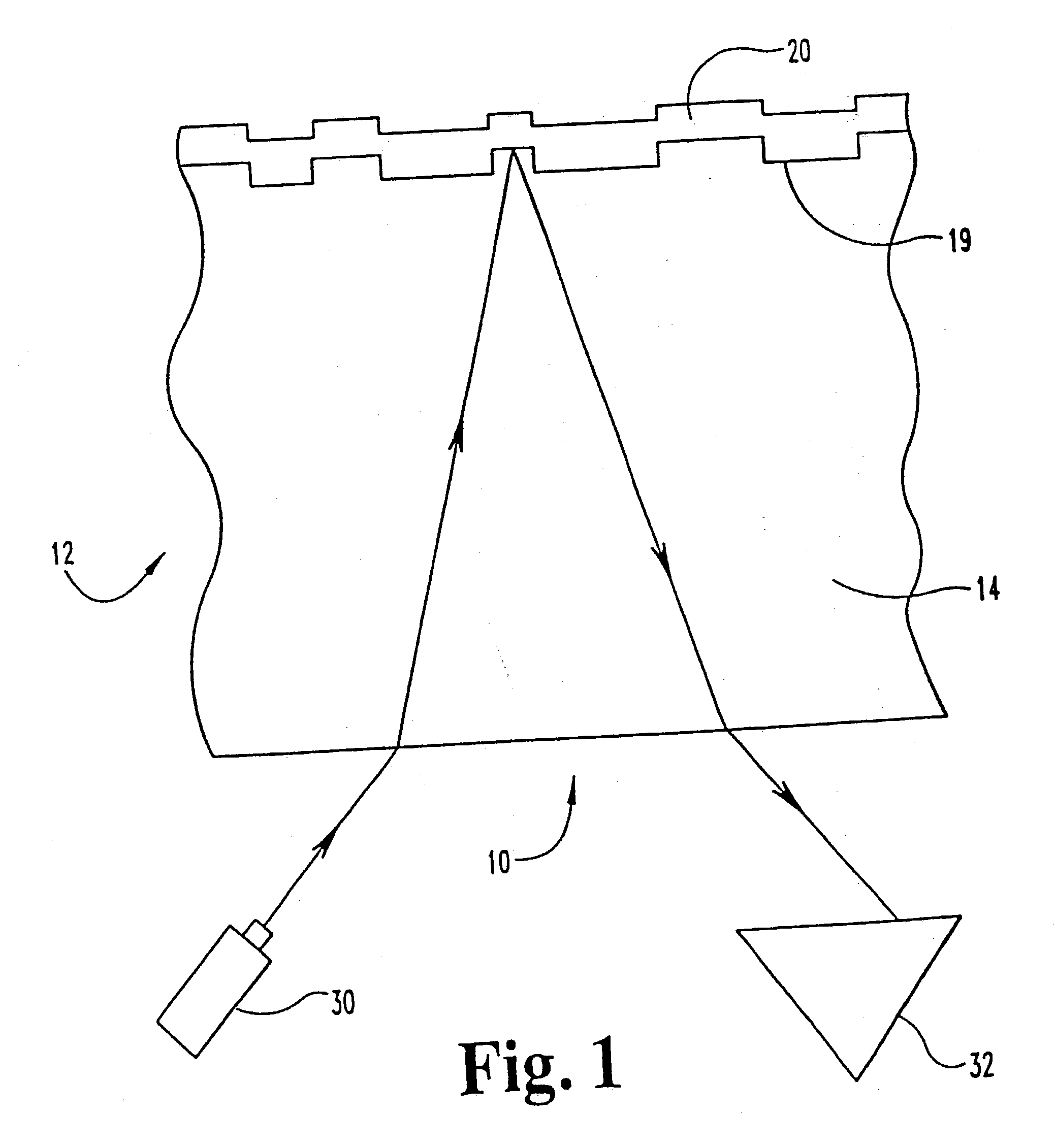
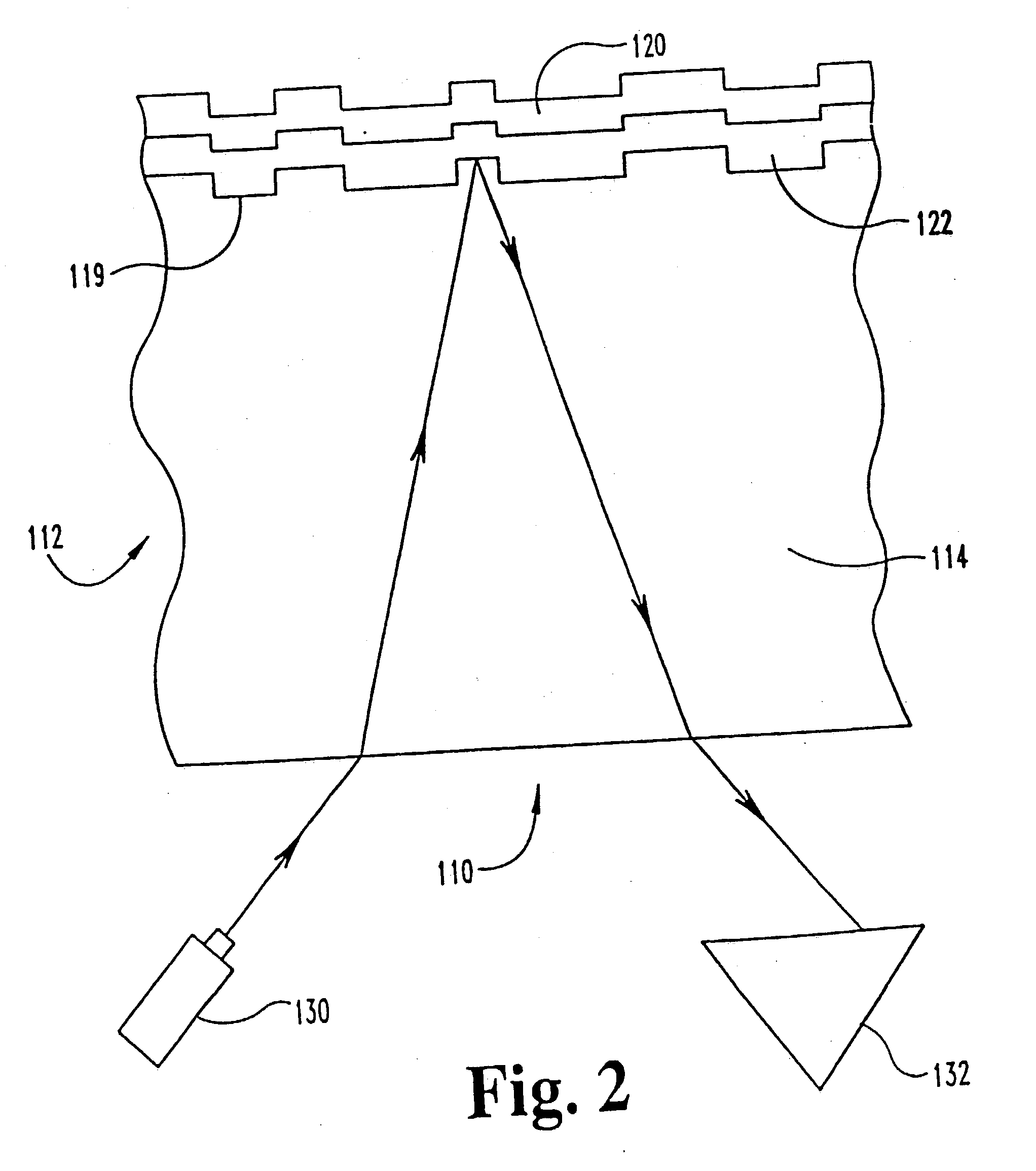
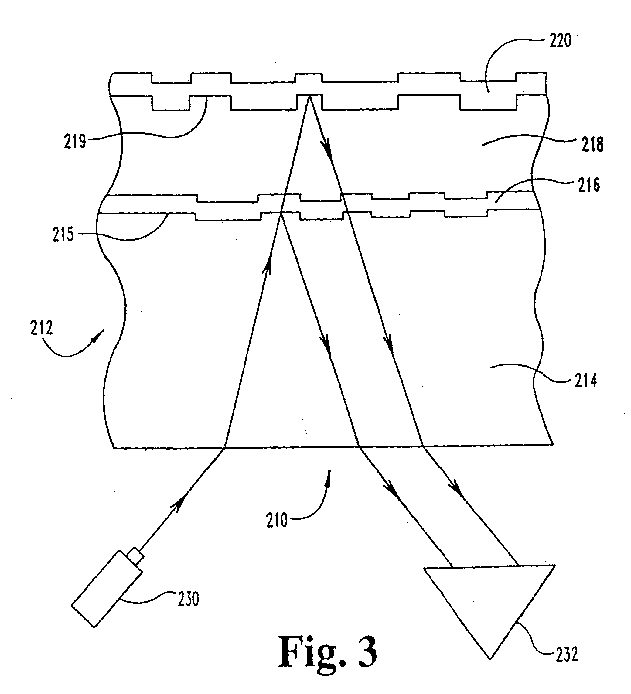
I. BACKGROUND OF THE INVENTION[0001] Four layers are generally present in the construction of a conventional, prerecorded, optical disc. A first layer is usually made from optical grade, polycarbonate resin. This layer is manufactured by well-known techniques that usually begin by injection or compression molding the resin into a disc. The surface of the disc is molded or stamped with extremely small and precisely located pits and lands. These pits and lands have a predetermined size and, as explained below, are ultimately the vehicles for storing information on the disc.[0002] After stamping, an optically reflective layer is placed over the information pits and lands. The reflective layer is usually-made of aluminum or an aluminum alloy and is typically between about 40 to about 100 nanometers (nm) thick. The reflective layer is usually deposited by one of many well-known vapor deposition techniques such as sputtering or thermal evaporation. Kirk-Othmer. Encyclopedia of Chemical Te...

Claims


Application Information

Patent Timeline
Patent Type & Authority Applications(United States)
IPC IPC(8): G11B7/258
CPCG11B7/258Y10T428/21G11B7/2595G11B7/259Y10T428/31678
Inventor NEE, HAN H.
Owner TARGET TECH
Learn More