Method for processing by laser, apparatus for processing by laser, and three-dimensional structure

processing method, applied in the direction of manufacturing tools, electric/magnetic/electromagnetic heating, conductive material removal by irradiation, etc., can solve the problem of difficult to define a material-removing region smaller than an irradiation region of light on the processing object, complicated process and conventional etching processing method. problem, to achieve the effect of reducing the number of processing steps, and improving the quality of the a technology a three-dimensional structure three-dimensional structure, three-dimensional structure, can solve the problem of three-dimensional structure, the problem of the processing object, the problem of the material removal region of the light-d a three-dimensional structure laser technology, applied in the field of laser processing method, laser processing method, three-dimensional structure, thr

Inactive Publication Date: 2003-11-20
RICOH KK
View PDF1 Cites 29 Cited by
  • Summary
  • Abstract
  • Description
  • Claims
  • Application Information

AI Technical Summary

Benefits of technology

0026] The inventors, as a result of intensive study, have newly found out a method to solve the problems in the conventional laser processing and to realize microfabrication. The method is a method that uses the relationship between a laser absorption layer and laser irradiation intensity distribution. Microfabrication to the laser irradiation region or smaller is enabled by this method. Further, according to this method, fine and micro amount processing to material, which is considered to be refractory material in the conventional laser processing method, can be realized without occurrence of flash, warp or the like.

Problems solved by technology

However, the conventional etching processing method by photolithography has a complicated process and requires a large number of processing.
Further, it also requires complicated process such as resist processing, exposure, development, baking or the like.
In this case, it is difficult to define a material-removing region smaller than an irradiation region of light on the processing object.
For this reason, when a micro region is processed and formed on the processing object by using the laser, the vicinity of an irradiation region of laser beam easily causes thermal deformation and fusion in low melting point material such as polymer, so that highly accurate processing is difficult.
Further, in brittle material such as glass and ceramic, there are cases where fracture or crack occurs in the irradiation region of laser beam, it has been difficult to form a fine shape on the processing object.
Furthermore, in the processing by harmonic of excimer laser or YAG laser, a processing range is generally defined only to material having high absorption to its laser wavelength, and thus the processing of the transparent material has been difficult, or it has been necessary that the material be processed by vacuum ultraviolet beam that cannot be used in the atmosphere.
Even in such a case, the processing has often required extremely high irradiation intensity of laser beam.
Moreover, it has been difficult to form a region smaller than the irradiation region of laser beam on the processing object even if the laser beam for processing is used, and thermal diffusion or the like sometimes has caused a processing region to have a larger width than the irradiation region of laser beam.
However, the transparent material has a long light permeability length and removal of micro amount of matter of the processing object has been difficult, and there have been cases where crack or the like occurred.
However, in this case, there has existed a problem that extremely large energy density was required and a laser light source with high energy in an extremely short pulse width was required.
Further, although it is possible to remove the matter of thin film layer formed on an upper surface of the processing object by a thin film processing method using a conventional laser ablation method, no consideration is paid to removing the matter on a surface of the processing object, which exists under the thin film layer, and forming a fine shape on a surface of processing object.
However, technology regarding fine structure processing of the laser irradiation region or smaller has not been known.
Further, the processing object may be made of brittle material.
When laser is used where laser beam for processing has the pulse width of 10 picoseconds or less, a thermal diffusion region can be restricted even for material such as metal having high-speed thermal conductivity due to the short pulse width.

Method used


Image

  • Method for processing by laser, apparatus for processing by laser, and three-dimensional structure
  • Method for processing by laser, apparatus for processing by laser, and three-dimensional structure
  • Method for processing by laser, apparatus for processing by laser, and three-dimensional structure

Examples


first embodiment

[0071] [First Embodiment]

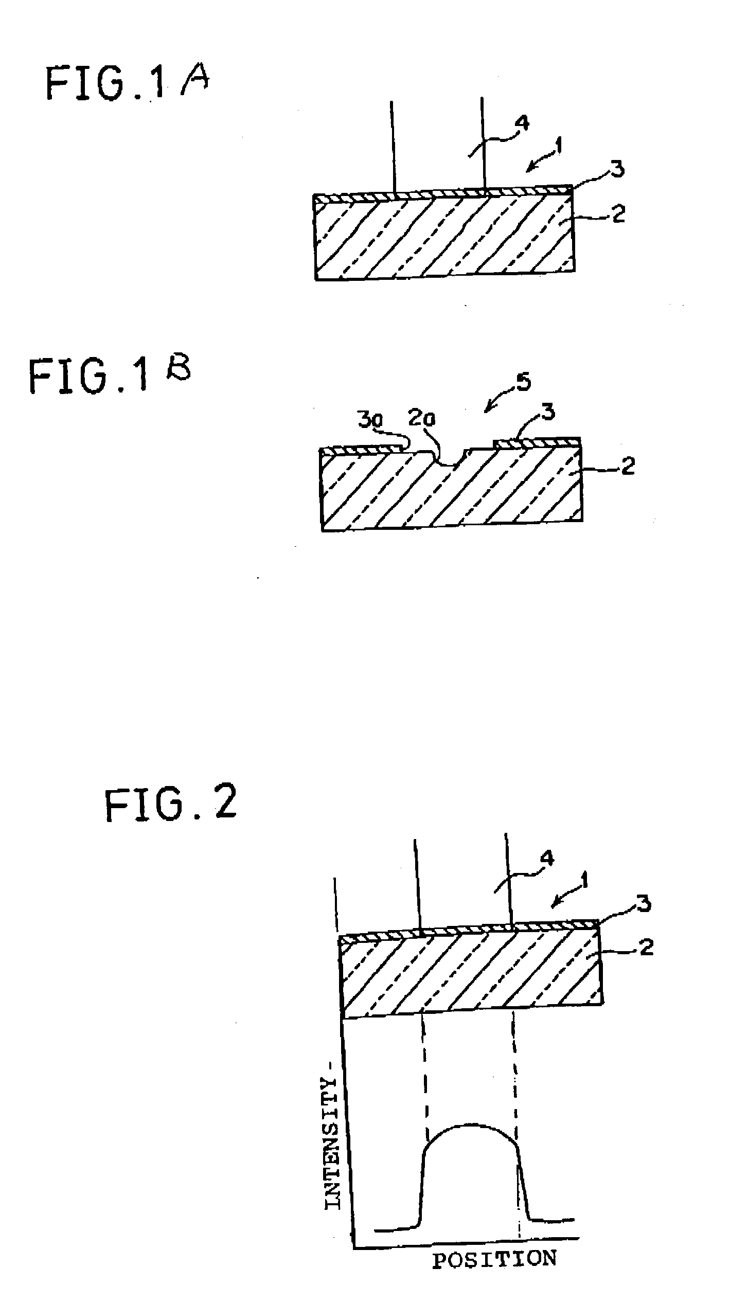
[0072] FIG. 1 is the exemplary view of a method for processing a three-dimensional structure according to a first embodiment of the present invention, FIG. 2 is the view showing the relationship between position of pore and width of pore in a fine shape processed and formed on a processing object and the intensity distribution of corresponding laser beam for processing.

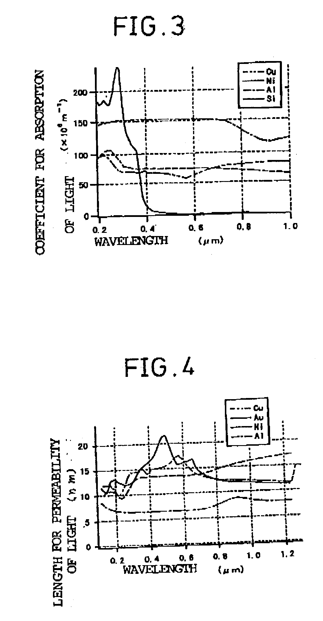
[0073] In the laser processing method of the first embodiment, a thin film 3 of metal as an absorptive thin film material layer is formed on a surface of a flat glass substrate 2 as the processing object first, as shown in FIG. 1A. Thus, a processing object (processing target) 1 is formed. The metal thin film 3 having high absorption to the laser beam for processing is used. At this point, it is desirable that a film thickness of metal thin film 3 be the order of a length for absorption of laser beam (length for permeability of light).

[0074] Next, laser beam for processing 4 is irradiated onto...

second embodiment

[0110] [Second Embodiment]

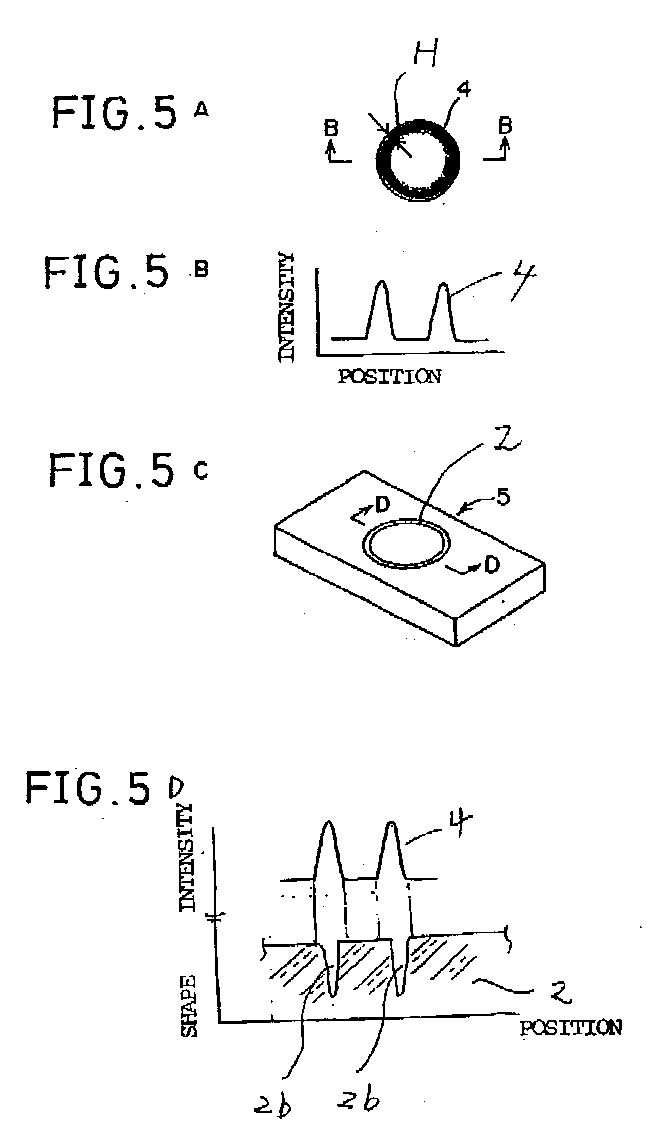
[0111] FIG. 5A is the plan view schematically showing the relationship between the irradiation shape of shaped laser beam for processing 4 and the intensity distribution of light. FIG. 5B is the exemplary view of the intensity distribution of light along B-B line. FIG. 5C is the perspective view showing the shape of processing object. FIG. 5D is the view showing the relationship between the micro region, which has been formed on the processing position of processing object by irradiating the laser beam for processing, and light intensity distribution.

[0112] In the second embodiment, laser irradiation light distribution of the laser beam for processing 4 is shaped by lenses, mirrors, a diffraction optical device, an optical mask, and the like, to have the state that the irradiation light distribution in laser beam irradiation region on the processing object has spatial and selective distribution.

[0113] For example, the laser beam is formed into ring beam whe...

third embodiment

[0120] [Third Embodiment]

[0121] FIG. 6A is the perspective view schematically showing the intensity distribution of laser beam for processing 4 used in the third embodiment. FIG. 6B is the perspective view of the three-dimensional structure 5 that has been processed by the laser beam for processing 4 having the intensity distribution in FIG. 6A.

[0122] The beam shape of laser beam for processing 4 is shaped by lenses, mirrors, a diffraction optical device, an optical mask, and the like, to have the linear-shaped beam shape in the laser irradiation region (processing region) on the processing object as shown in FIG. 6A.

[0123] The linear-shaped beam shape can be easily realized by using cylindrical lenses, for example. The shaped laser beam for processing 4 is irradiated on the surface of processing region of the processing object. Thus, as shown in FIG. 6B, a linear-shaped concave portion 2c having a narrower width than the irradiation width of laser beam for processing 4 is formed in...


PUM

PropertyMeasurementUnit
wavelengthaaaaaaaaaa
thicknessaaaaaaaaaa
pulse widthaaaaaaaaaa

Abstract

A laser processing method capable of performing fine and highly accurate processing by low energy is obtained. The invention relates to the laser processing method where laser beam for processing (4) is irradiated on a processing object (2) and the laser beam for processing (4) directly removes a part of the processing object (2). The processing object (2) is made of a glass substrate, metal thin film (3) having high absorption to laser beam for processing (4) is formed on a surface of glass substrate, into which laser beam for processing (4) is made incident, the laser beam for processing (4) is irradiated from a surface of metal thin film (3), and matter is directly removed by irradiation of laser beam onto the processing object (2) in order to form a region finer than an irradiation region of laser beam for processing (4) on the processing object (2).

Description

[0001] 1. Field of the Invention[0002] The present invention relates to a method for processing by laser, in which laser beam is irradiated on a processing object to directly form a fine shape on the processing object, an apparatus for processing by laser and a three-dimensional structure on which a fine shape is formed by the apparatus.[0003] 2. Description of the Prior Art[0004] Conventionally, etching technology for using photolithography has been mainly used as a processing method that forms a highly accurate three-dimensional shape of a fine part as the processing object. In this processing method, resist material is coated on a substrate of processing object, light is selectively irradiated on the resist material, solution processing is performed, and a desired pattern is thus formed. In the method, etching is subsequently performed to remove a resist region other than a light irradiation region, and thus forming the three-dimensional shape.[0005] In this processing method, tw...

Claims


Application Information

Patent Timeline
Patent Type & Authority Applications(United States)
IPC IPC(8): B81C1/00B23K26/00B23K26/06B23K26/073B23K26/18B23K26/382C03C17/00C03C17/06C03C23/00H05K1/03H05K3/00H05K3/02
CPCB23K26/0635B23K26/0734C03C17/002C03C17/06C03C23/0025Y10T428/24917C03C2218/328C03C2218/355H05K1/0306H05K3/0029H05K3/027C03C2217/25B23K26/0624
Inventor YAMADA, YASUFUMIMIDORIKAWA, KATSUMIKUMAGAI, HIROSHI
Owner RICOH KK
Why Eureka
Try Eureka