Composition and method for removing photoresist and/or resist residue using supercritical fluids

a supercritical fluid and photoresist technology, applied in the direction of detergent compounding agents, cleaning using liquids, instruments, etc., can solve the problems of less desirable plasma etching procedure for resist removal, less visible residues in post-ash plasma etching, etc., and achieve the effect of removing photoresist and/or resist residues from high aspect ratio openings such as submicron grooves, narrow crevices, etc., without damaging the structure being produced

Inactive Publication Date: 2004-01-22
SCP GLOBAL TECH INC
View PDF37 Cites 74 Cited by
  • Summary
  • Abstract
  • Description
  • Claims
  • Application Information

AI Technical Summary

Problems solved by technology

While the high temperature in the plasma process chamber oxidizes the photoresist and removes it, the plasma etch process leaves post-ash residues--undesirable byproducts from the reaction of the plasma gases, reactant species and the photoresist.
Moreover, the plasma etch procedure for resist removal is less desirable for substrates having low dielectric constant (or "low-k") films as insulating layers.
Nevertheless, the industry lacks a first-rate method of removing photoresist and/or resist residue from high aspect ratio openings such as submicron grooves, narrow crevices etc. without damaging the structure being produced.
This not only speeds up the wafer processing but also results in a decreased consumption of solvents and/or water used in cleaning, rinsing and drying.
Until now, however, the use of scCO.sub.2 in photoresist removal processes has not been successfully achieved.
This lack of success is due to the fact that scCO.sub.2 itself is a very poor solvent for polar residues such as resist and/or resist residues found on wafer surfaces.
Many of these processes are not cost effective for commercial use in that they require extended processing durations overly high energy costs, or use of prohibitively large quantities of process chemicals.
Others expose substrates to temperatures and/or pressures and/or chemical environments that can degrade the electrical performance of the integrated circuits manufactured using the substrates.
Others may

Method used


Image

  • Composition and method for removing photoresist and/or resist residue using supercritical fluids
  • Composition and method for removing photoresist and/or resist residue using supercritical fluids
  • Composition and method for removing photoresist and/or resist residue using supercritical fluids

Examples


example 2

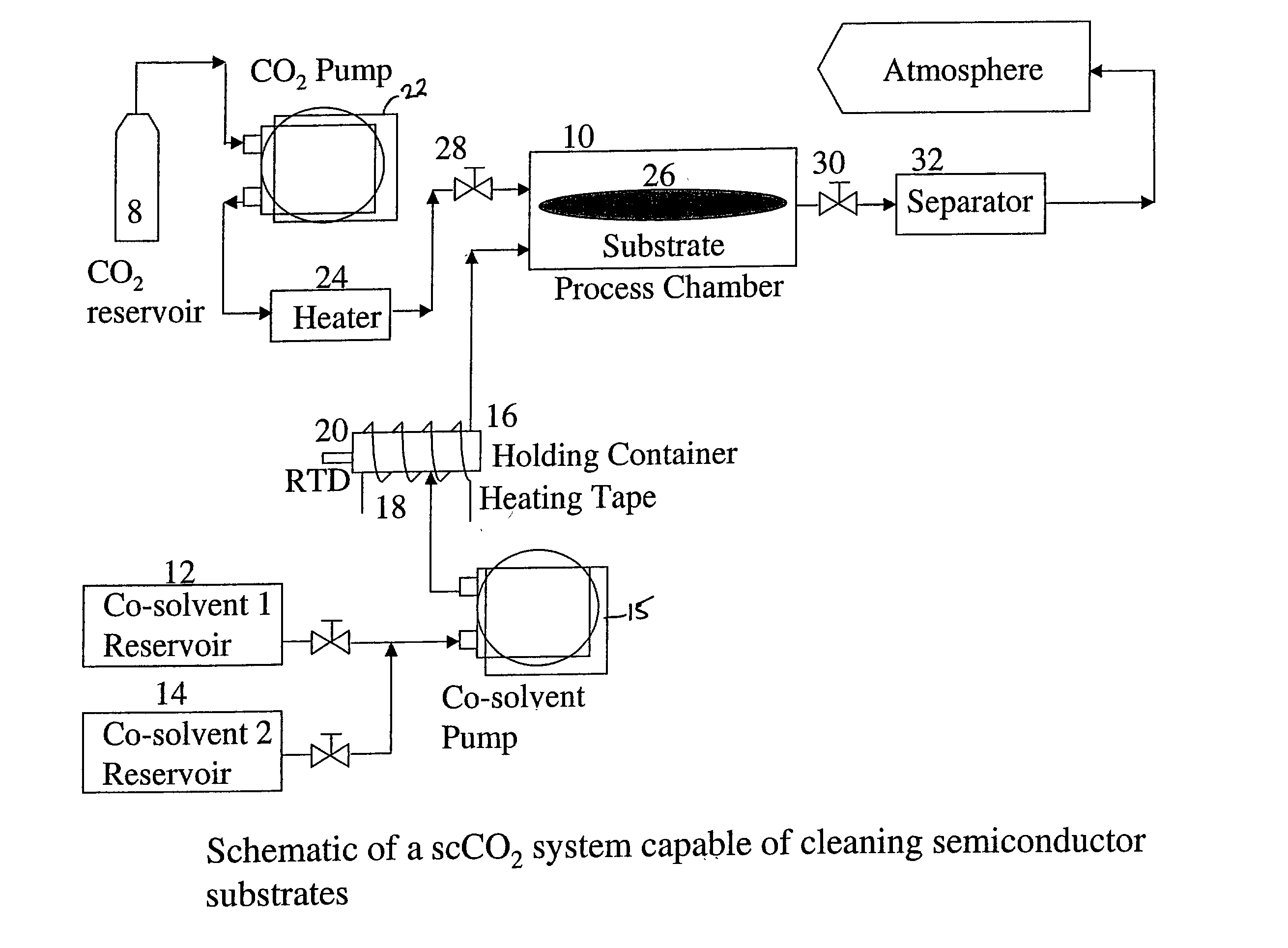
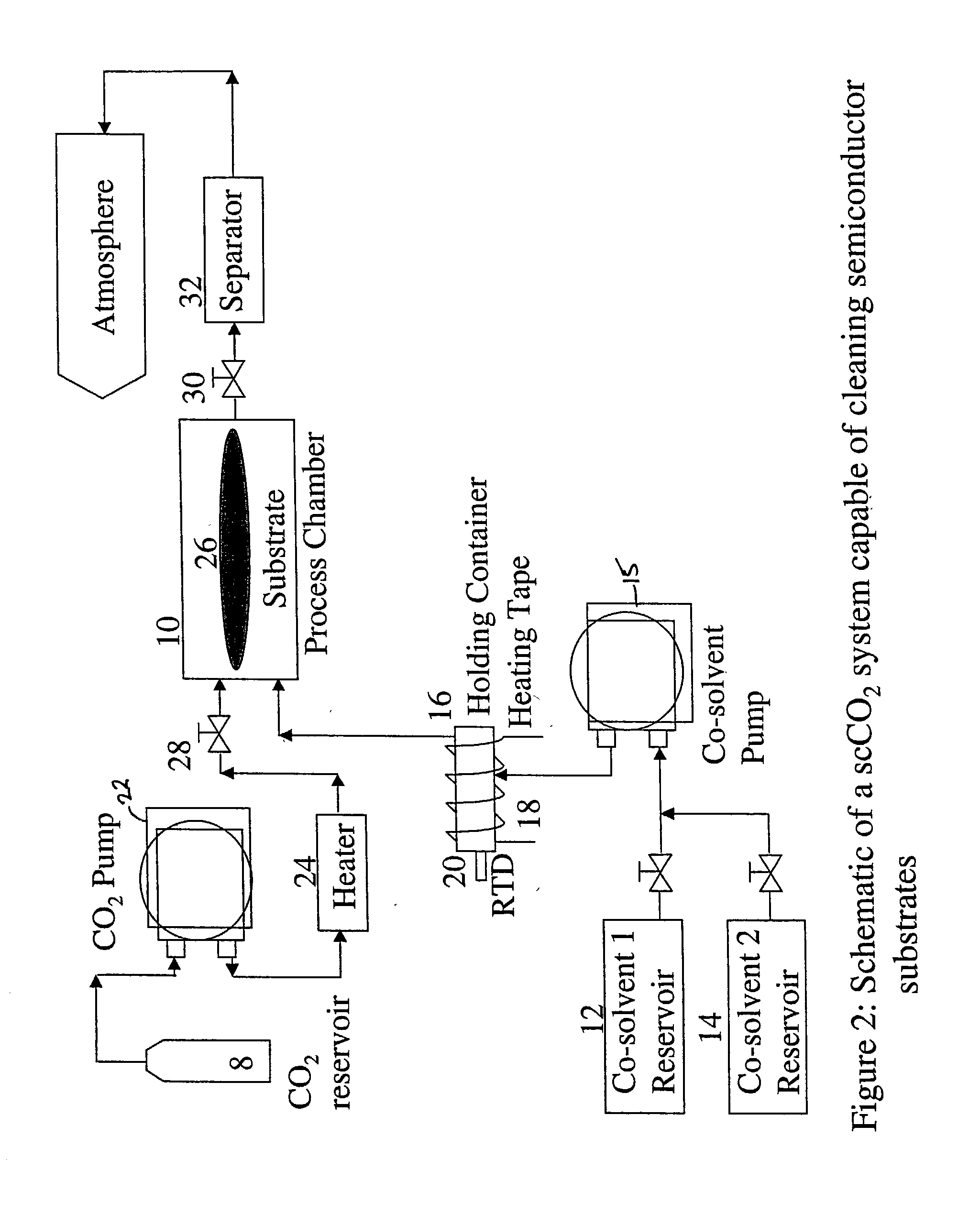
[0056] In the second example, the co-solvent mix is unchanged but is introduced into the process chamber in higher amounts at the start of the run and the complete process is run without any static dwell in the process chamber. A substrate having a hard baked I-line photoresist that was DUV stabilized using UV lamps to achieve 100% cross-linking was placed in the process chamber. A co-solvent I composition of 40% (by weight) 1,2-Butylene Carbonate, 30% Dimethyl Sulfoxide, and 30% of 30% hydrogen peroxide was mixed at a temperature of 50.degree. C. This mixture was made to flow into the process chamber and onto the substrate at a rate of 20 g / min for approximately 30 seconds. Supercritical carbon dioxide was caused to flow into the chamber with the co-solvent 1 at a flow rate of 60 g / min to have a total fluid flow rate into the process chamber at 80 g / min. Subsequently the co-solvent 1 flow rate was decreased to 2.4 g / min and the supercritical carbon dioxide flow rate increased to 77...

example 3

[0059] The third example is similar to Example 2, but differs in that a different cosolvent 1 composition was used. A substrate having a hard baked I-line photoresist that was DUV stabilized using UV lamps to achieve 100% cross-linking was placed in the process chamber. A co-solvent 1 composition of 40% (by weight) 1,2-Butylene Carbonate, 40% Benzyl Alcohol, and 20% of 30% hydrogen peroxide was mixed at a temperature of 50.degree. C. This mixture was made to flow into the process chamber and onto the substrate at a rate of 20 g / min for approximately 45 seconds. Supercritical carbon dioxide was caused to flow into the chamber with the co-solvent 1 at a flow rate of 60. g / min to have a total fluid flow rate into the process chamber at 80 g / min. Subsequently the co-solvent 1 flow rate was decreased to 2.4 g / min and the supercritical carbon dioxide flow rate-increased to 77.6 g / min. for the next 3 minutes and 15 seconds. The operating temperature and pressure within the chamber were 110...

example 4

[0062] The fourth example utilized the same co-solvent 1 composition as used in Example 2, but the composition was used on a substrate having different characteristics. In this example, the blanket photoresist layer removed was a 6000 .ANG. thick DUV 5 photoresist layer on top of a polysilicon layer which covers a silicon dioxide layer on top of the silicon wafer substrate. The photoresist was subjected to a high dose implant of boron at 10 keV to a dosage level of 3.times.10.sup.15 atoms / cm.sup.2. A co-solvent 1 composition of 40% (by weight) 1,2-Butylene Carbonate, 30% Dimethyl Sulfoxide, and 30% of 30% hydrogen peroxide was mixed at a temperature of 50.degree. C. This mixture was made to flow into the process chamber and onto the substrate at a rate of 8 g / min for 4 minutes. The co-solvent 1 mixture was carried into the process chamber by supercritical carbon dioxide at a flow rate of 72 g / min to have a total fluid flow rate into the process chamber at 80 g / min. The operating tem...


PUM

PropertyMeasurementUnit
Fractionaaaaaaaaaa
Dielectric constantaaaaaaaaaa

Abstract

A method of removing photoresist and/or resist residue from a substrate includes exposing the substrate to a supercritical fluid in combination with a co-solvent mixture comprising an organic solvent and an oxidizer. In one embodiment, the supercritical fluid is supercritical carbon dioxide and the co-solvent mixture includes 1,2-Butylene Carbonate, Dimethyl Sulfoxide and hydrogen peroxide. If desired, supercritical carbon dioxide in combination with a second co-solvent mixture may be subsequently applied to the substrate to rinse and dry the substrate. In one embodiment, the second co-solvent mixture includes isopropyl alcohol.

Description

[0001] The present invention relates to supercritical fluids and, in particularly, to compositions and methods using supercritical fluids to remove photoresist and / or resist residues and associated materials from semiconductor substrates.BACKGROUND OF THE DISCLOSURE[0002] During the process of fabricating semiconductor integrated circuits, organic photoresist material may be applied to a semiconductor substrate as a precursor to formation of features on the substrate using photolithography techniques. Often additional coatings, for example an anti-reflective coating known in the industry as BARC [Back Antireflective Coating], are also applied to the substrate to enhance the lithography process.[0003] Once lithography is completed, the resist, BARC and other coatings used for the lithography steps must be removed from the substrate. A common technique for photoresist removal involves placing the substrate in an asher and burning the resist and associated coatings using a gaseous plas...

Claims


Application Information

Patent Timeline
IPC IPC(8): G03F7/42
CPCG03F7/422G03F7/423H01L21/02101G03F7/426G03F7/425
Inventor SEGHAL, AKSHEY
Owner SCP GLOBAL TECH INC
Why Eureka
Try Eureka