Megasonically energized liquid interface apparatus and method

Inactive Publication Date: 2004-01-29
CAWLFIELD B GENE
View PDF7 Cites 22 Cited by
  • Summary
  • Abstract
  • Description
  • Claims
  • Application Information

AI Technical Summary

Benefits of technology

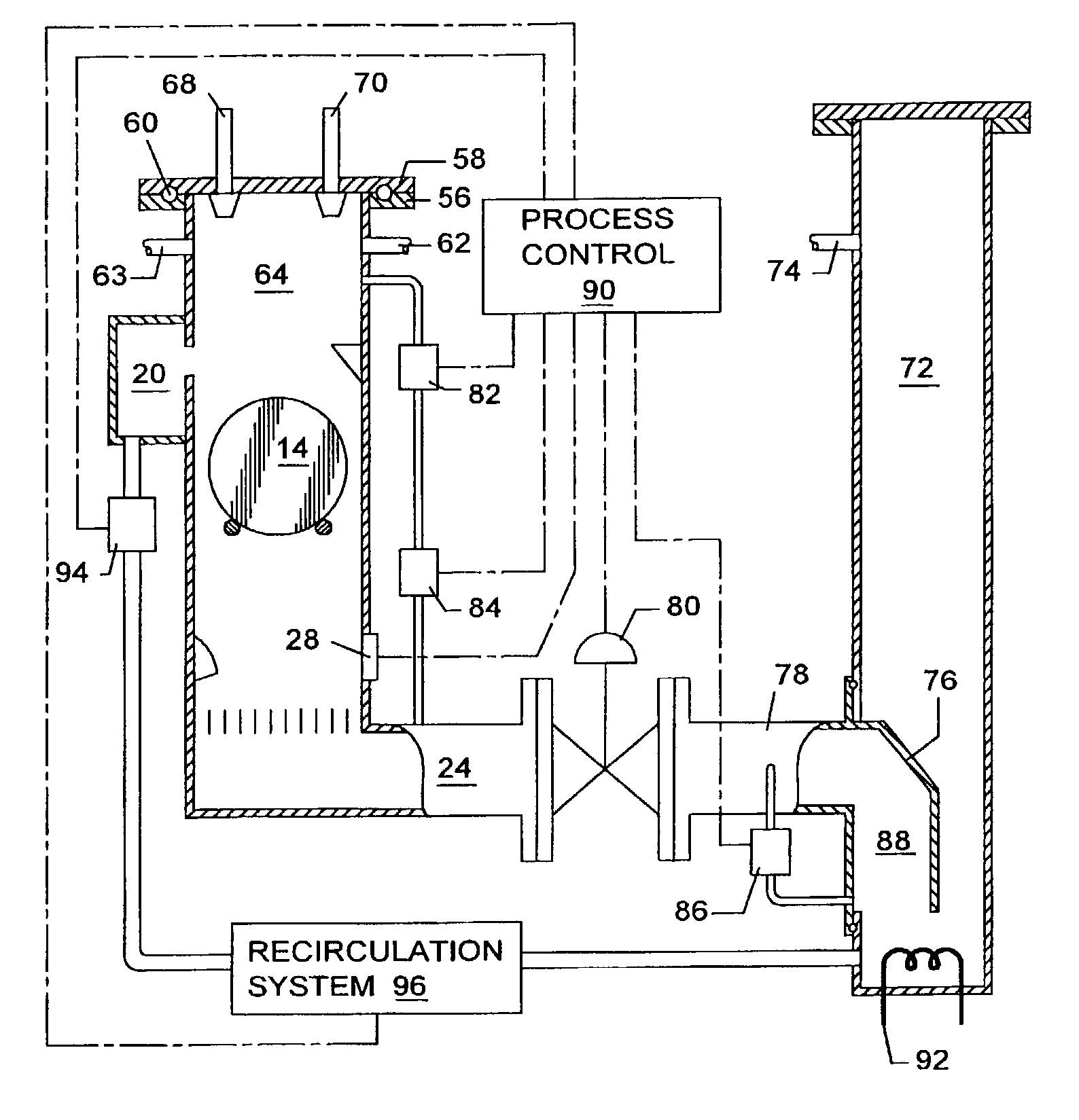
0040] An alternative apparatus is disclosed in FIG. 7 for connecting the process tank 12 and the home container 72 when only a single process liquid is used. In this embodiment, a vertical riser 98 connects to the bottom of the process tank 12, replacing the butterfly valve 80 and downcomer 76 of FIG. 5. A pressure connection 74 on the home container 72 allows the use of varying positive pressure to drive process fluid into and out of the process tank 12 from the home container 72. As an alternative, the process tank 12 can be sealed and provided with a pressure connection 62 as shown in FIGS. 5 and 6, and vacuum and venting can be used in combination with positive pressure to move the process liquid back and forth, as previously described. The riser 98 is preferably located near one side wall 100 of the home container 72, with the opposite side wall 102 tapered toward the riser 98, so that the bottom 104 of the home container is only slightly wider than the riser 98. This configuration is use to minimize liquid inventory remaining in the home container after filling the process tank and providing additional liquid for overflow and recirculation. The opposite sid

Problems solved by technology

A particle one fourth the size of a pattern width is considered unacceptable.
This lowers the allowable particle size to a level that present cleaning methods either have trouble achieving, or fail to achieve altogether.
Isopropyl alcohol (IPA) is used to displace water at the wafer surface in an attempt to alter the surface chemistry dynamics for improved particle removal, but the pseudo-equilibrium effect remains to a lesser degree, and the use of IPA is a drawback due to IPA's environmental and fire hazards.
In addition, the equipment is complex and expensive to construct and operate, and the time required to clean each wafer is longer than that in most methods.
The generally accepted explanation as to how these methods work is that local low pressure points in the sonic energy field cause cavitation bubbles to form in a liquid, which then collapse causing shock waves that dislodge and remove particles from the surface of the workpiece.
This method requires complex apparatus with many more parts than competing methods, and is much more expensive to construct and to operate.
Also, this method only cleans one side of the wafer at a time, and cannot be easily adapted to handle multiple wafers at a single time, resulting in very low throughput compared to other methods.
This method obviously cannot be adapted to cleaning non-flat workpieces, that is, those with significant variations in surface height.
However, the particle count could be significa

Method used


Image

  • Megasonically energized liquid interface apparatus and method
  • Megasonically energized liquid interface apparatus and method
  • Megasonically energized liquid interface apparatus and method

Examples


example 2

[0053] the test procedure of Example 1 was repeated using a total of ten cycles. Again, post-treatment testing indicated zero particles remaining.

example 3

[0054] the test procedures of Example 1 and Example 2 were repeated using equal up and down sweep times of one second duration, for a total particle removal time of only ten seconds and twenty seconds, respectively. Once again, post-treatment testing indicated zero particles remaining.

[0055] EXAMPLE 4: the test procedure of Example 1 was repeated, but only two cycles were performed (four total sweeps) of equal one second duration. Post-treatment testing showed particles remaining, with substantially uniform percentage reduction in particle count across the photomask surface.

[0056] The example results are critically important for photomask production. The photomask pattern is printed on every die on a semiconductor wafer. Even a single defect on a photomask could kill every die on the wafer. The examples show that the method of the invention can produce photomasks with zero particles remaining, and do so consistently. The invention is also suitable for semiconductor wafer processing...


PUM

PropertyMeasurementUnit
Temperatureaaaaaaaaaa
Timeaaaaaaaaaa
Pressureaaaaaaaaaa

Abstract

Apparatus and method for removing material adhering to a workpiece are disclosed. A process liquid and a discontinuous phase are placed in a process tank adapted to receive a workpiece. The interface between the process liquid and the discontinuous phase is energized with megasonic energy, and the interface is contacted with and moved relative to the workpiece in a linear direction at a controlled rate, preferably across all of the workpiece. Liquid in the interface is optionally removed from the process tank at predetermined times to remove entrained particles. Numerous drying schemes can be used to reduce or eliminate formation of droplets and to speed drying time.

Description

BACKGROUND OF INVENTION[0001] This invention relates in general to apparatus and processes using megasonic energy. In particular, the invention relates to a wet process for removing material adhering to a workpiece surface by repeated exposure of the workpiece surface to the interface between a liquid and a discontinuous phase while the interface is excited by megasonic energy.[0002] Advances in semiconductor manufacturing have resulted in ever shrinking geometries, which have demanded a corresponding increase in cleanliness for equipment, photomasks and wafers to prevent unacceptable defect levels. A particle one fourth the size of a pattern width is considered unacceptable. Present geometries already force visible light microscopes to struggle in order to provide practical inspection and description of all small particles of concern. One of the more recent photolithographic methods, known as phase shift photomask, can even create pattern geometry smaller than a wavelength of the u...

Claims


Application Information

Patent Timeline
IPC IPC(8): B08B3/12H01L21/00
CPCB08B3/12H01L21/67086H01L21/67057B08B3/048
Inventor CAWLFIELD, B. GENE
Owner CAWLFIELD B GENE
Why Eureka
Try Eureka