Virtual wells for use in high throughput screening assays
Inactive Publication Date: 2004-01-29
GARYANTES TINA K
View PDF35 Cites 49 Cited by
Summary
Abstract
Description
Claims
Application Information
AI Technical Summary
This helps you quickly interpret patents by identifying the three key elements:
Problems solved by technology
Method used
Benefits of technology
Benefits of technology
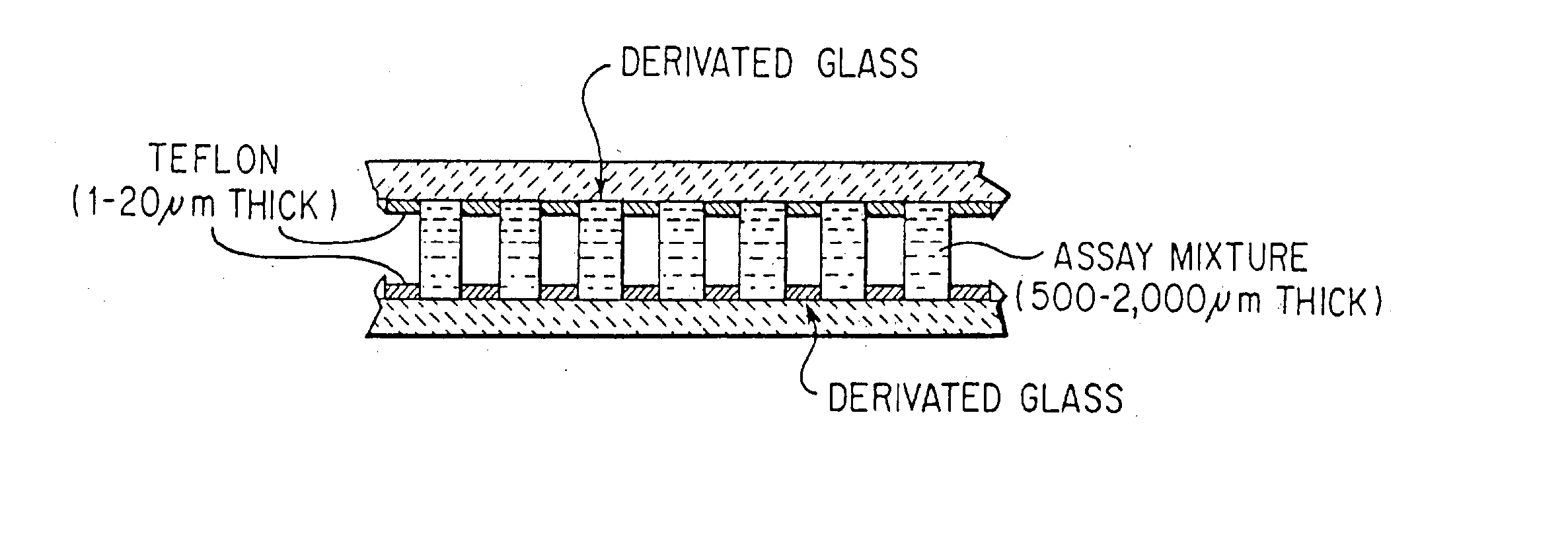
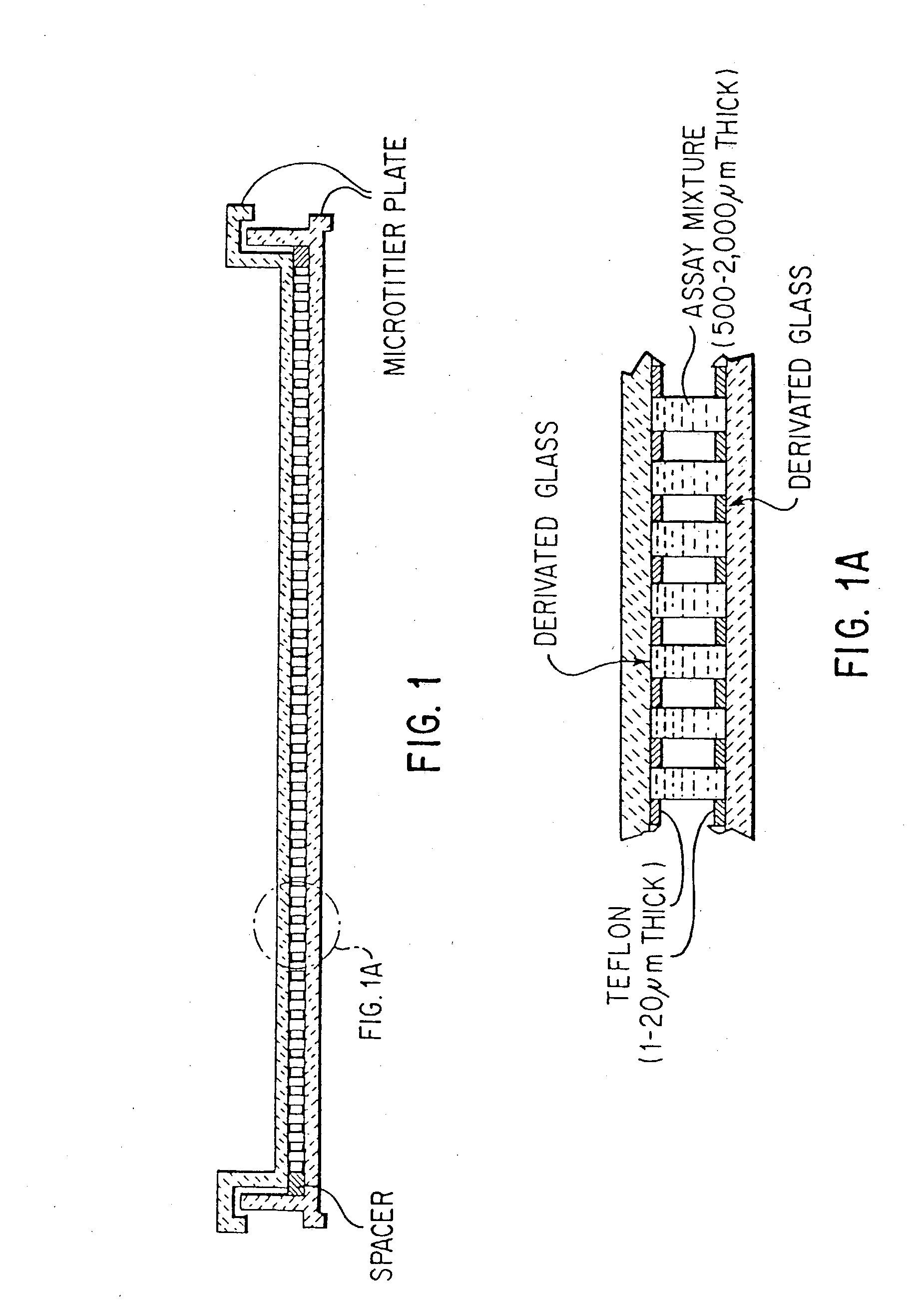
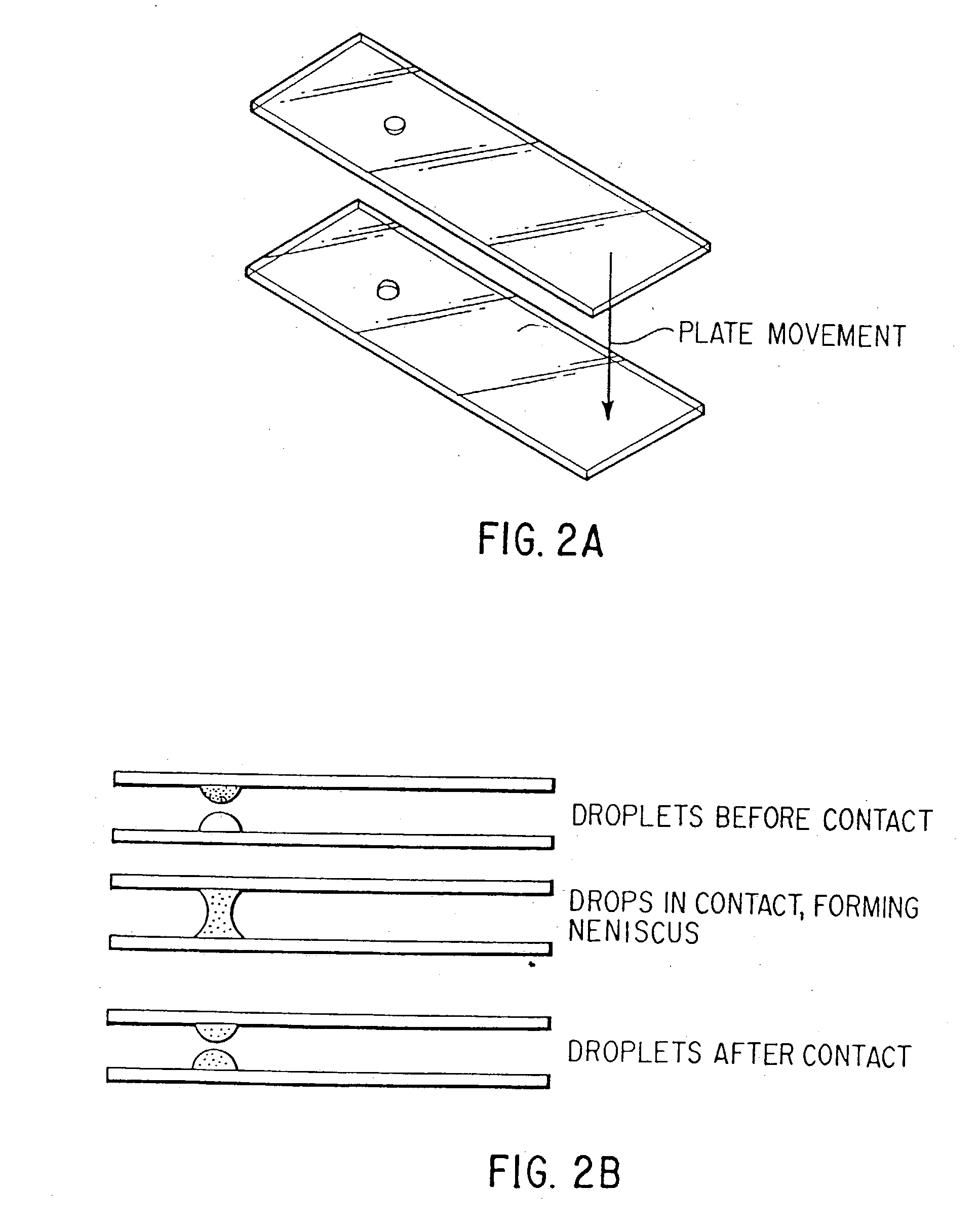
[0014] The present invention provides microtiter-like plates containing "virtual wells." Virtual wells could be any surface modification such as protrusions or slight indentations (e.g., having a depth of between 0.5 nm to 500 .mu.m, preferably about 3 nm to about 200 .mu.m, more preferably about 10 nm to about 100 .mu.m, and even more preferably about 10 nm to about 50 .mu.m), as well as chemical modifications, binding sites, or other discontinuities present in slight indentations, on the plate surface that orders or retains fluid drops into a defined spatial array. Typically, the virtual wells are formed by an arrangement of relatively hydrophilic domains within relatively hydrophobic fields. Solvated samples (compounds) and assay reagents are confined to the more hydrophilic domains of the virtual wells by the edges of the more hydrophobic fields. The use of virtual wells allows one to run high throughput screening assays that require the capture and washing of an assay component prior to reading, as well as assays simply requiring the mixing of components and reading, with assay mixtures having volumes on the order of about 10 nl to 10 .mu.l. The virtual wells can also be used to effect near simultaneous addition or subtraction of fluid from all wells in a virtual well microtiter-like plate to enable screening fast kinetic and flash reactions. The virtual wells allow one to repeatedly transfer a known volume from each well of a spatially defined array of solutions into a second array in a single step and to precisely aliquot small volumes of compounds or reagents to multiple assays. The present invention also provides a means for controlling evaporation and providing a reproducible optical path. The present invention also includes methods of high throughput screening utilizing microtiter-like plates containing virtual wells.
[0015] The present invention also provides an inexpensive, disposable device for transferring small volumes of an entire array of compounds from a first microtiter-like plate to other microtiter-like plates multiple times, preserving the spatial arrangement of the compounds without risking contamination of samples or requiring excessive washing time. Methods of manufacturing and using the device are also provided.
Problems solved by technology
Higher density plates typically have wells that hold lower volumes, but such plates are subject to more limitations in that few such plates are available with filters in the bottom and assay preformance is often compromised.
Thus, for plates with more than 384 wells, it is currently not feasible to run biological assays requiring a capture and wash step and moving fluids into and out of the narrow wells of such plates requires very precise pipetting.
While it is desirable to decrease the size of wells in current microtiter plates, there are problems associated with doing so, including, e.g., difficulty pipetting fluids into confined spaces, inadequate and slow mixing, difficulty effecting separations, rapid evaporation times, and limited signal strength during measurement.
Another limitation to the miniaturization of current screening systems is that of evaporation of the reagents during dispensing of the reagents.
The humidified environment is difficult to regulate, corrosive to automated equipment, and messy due to condensation.
It is difficult to find a truly non-miscible solvent to float on the broad variety of chemicals typically tested in a pharmaceutical screen.
The problem of dispensing an array of small volumes containing compounds of interest in a functional form for screening has been a major obstacle toward miniaturization.
The prior art pin tools or pin replicators are not ideal because they need to be washed (leading to possible contamination and loss of time), work at large volumes, do not have the accuracy needed, or are too expensive.
In addition, the prior art pin tools do not act as a reusable lid for the storage of low volume (1-2 .mu.l) compound arrays.
They are very slow and, like the prior art pins, they also need to be washed, leading to possible contamination and loss of time.
Method used
Image
Click on the blue label to locate the original text in one second.
Reading with bidirectional positioning of images and text.
Examples
example 2
Transfer of Fluid Multiple Times From Virtual Wells
[0241] 5 .mu.l of .sup.33P-labeled H.sub.2O containing Malachite Green (to make it easier to see the H.sub.2O) was added to virtual wells on a glass slide. The slides used were commercially available TEFLON.RTM. coated glass slides (Cell Line). The TEFLON.RTM. was patterned so as to leave areas of glass exposed having a diameter of 2 mm. Fluid was transferred from the wells of this slide five successive times to five other slides by moving the other slides into close proximity to the first slide. The first transfer was done without a spacer; the next four transfers were done with a 40 mil spacer. The slides were dried, wrapped in plastic wrap, and measured on an Instantlmager from Packard. The transfer variance on any given slide was between 4% and 10% and the variance across all five slides was 10%.
[0242] The above-described experiment was repeated with DMSO rather than H.sub.2O as the solvent and with the virtual wells in the top ...
[0243] The evaporation of a drop of water (approximately 20 nl to 30 nl) as a function of room temperature, room humidity, and the surface temperature of the slide on which the drop is placed was studied. 30 drops were dispensed simultaneously by piezo pipetting tip onto the surface of a glass slide and the time until the last drop evaporated was monitored. The results are shown in Table 3.
[0244] It can be seen from Table 3 that cooling the surface of the slide resulted in substantially increasing the time until the last drop evaporated. Of course, the surface of the slide cannot be cooled indefinitely; at some point con...
example 4
[0247] DMSO, labeled with a known concentration of .sup.33P-ATP, and present in a spatial array in virtual wells, was spotted onto glass slides using devices having pins that were made of gold coated tungsten wire. The diameter of the pins was varied in order to determine the effect of varying the diameter on the amount of fluid transferred. The device was manipulated by hand. The results are shown in Table 5.
PUM
Abstract
Microtiter-like plates containing virtual wells formed by an arrangement of relatively hydrophilic domains within relatively hydrophobic fields are provided. Assay mixtures are confined to the hydrophilic domains of the virtual wells by the edges of the hydrophobic fields. The use of virtual wells allows one to perform homogeneous and capture and wash high throughput screening assays with assay mixtures having volumes on the order of about 100 nl to 10 mu. Virtual wells also provide a means of easily moving fluids, which is particularly useful for simultaneous additions needed for kinetic studies and flash detection and washing. Methods for controlling evaporation during the dispensing of reagents as well as during incubation of high throughput screening utilizing microtiter-like plates containing virtual wells are also provided. The present invention also provides an inexpensive, disposable device for transferring small volumes of an entire array of compounds from a first microtiter-like plate to a second microtiter-like plate, preserving the spatial arrangement of the compounds. Methods of manufacturing and using the device are also provided.
Description
[0001] The present application claims priority from U.S. Provisional Patent Application Serial No. 60 / 073,697, filed Feb. 4, 1998, and U.S. Provisional Patent Application Serial No. 60 / 087,721, filed Jun. 2, 1998, the disclosures of which are incorporated herein by reference, in their entireties.STATEMENT REGARDING FEDERALLY-SPONSORED R&D[0002] Not applicableREFERENCE TO MICROFICHE APPENDIX[0003] Not applicable[0004] The present invention is directed to novel microtiter-like plates having a patterned arrangement of relatively hydrophilic domains within a relatively hydrophobic field that can be used in improved methods of high throughput screening of biological materials. The invention covers the plates and their uses for dispensing and moving fluids and for running high throughput screens. Also claimed are methods for controlling evaporation based on cooling the plates to the dew point during the dispense and limiting evaporation during incubation by providing a humidifying buffer ...
Claims
Application Information
Patent Timeline
Application Date:The date an application was filed.
Publication Date:The date a patent or application was officially published.
First Publication Date:The earliest publication date of a patent with the same application number.
Issue Date:Publication date of the patent grant document.
PCT Entry Date:The Entry date of PCT National Phase.
Estimated Expiry Date:The statutory expiry date of a patent right according to the Patent Law, and it is the longest term of protection that the patent right can achieve without the termination of the patent right due to other reasons(Term extension factor has been taken into account ).
Invalid Date:Actual expiry date is based on effective date or publication date of legal transaction data of invalid patent.

