Method of forming a barrier layer of a tunneling magnetoresistive sensor

a tunneling magnetoresistive and sensor technology, applied in the field of tunneling magnetoresistive (tmr) sensors, can solve the problems of inability to use tmr sensors in practice as submicron-sized read sensors for magnetic recording at high densities, difficulty in minimizing collisions of few oxygen atoms in plasma, and difficulty in controlling optimal oxygen doping into the bilayer film

Inactive Publication Date: 2004-05-27
GLOBALFOUNDRIES INC
View PDF18 Cites 56 Cited by
  • Summary
  • Abstract
  • Description
  • Claims
  • Application Information

AI Technical Summary

Problems solved by technology

Unfortunately, such TMR sensors cannot be used in practice as submicron-sized read sensors for magnetic recording at high densities, since R.sub.JA.sub.J must be around 4 .OMEGA.-.mu.m.sup.2 in order to prevent electrostatic discharge (ESD) damage to the sensors.
The DC magnetron reac

Method used


Image

  • Method of forming a barrier layer of a tunneling magnetoresistive sensor
  • Method of forming a barrier layer of a tunneling magnetoresistive sensor
  • Method of forming a barrier layer of a tunneling magnetoresistive sensor

Examples


Embodiment Construction

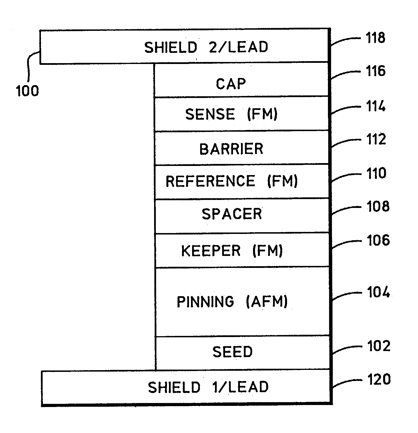
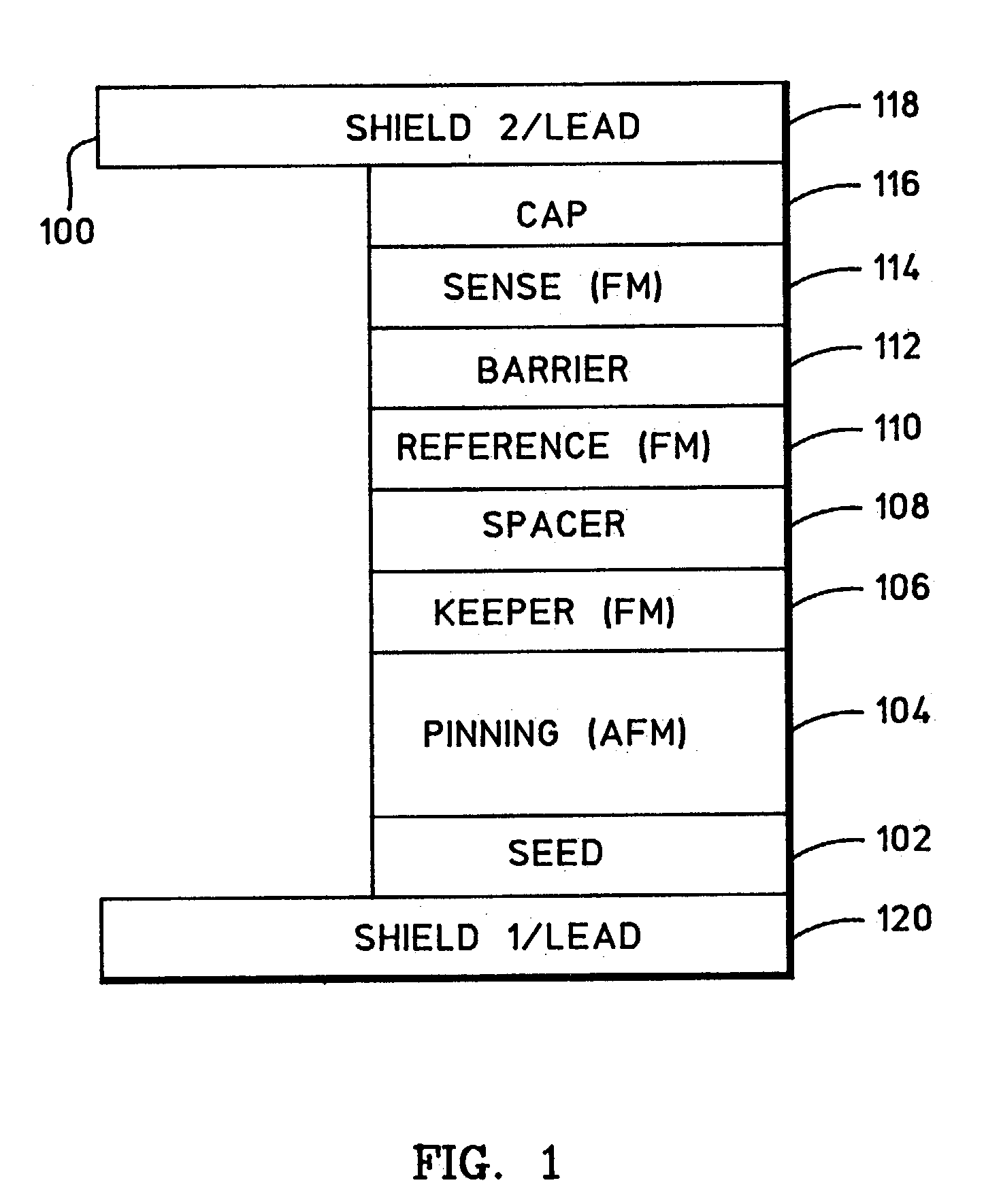
. In the fabrication process of the TMR sensor, the TMR sensor is deposited on a bottom FM Ni--Fe (.about.1 .mu.m) shield layer in the integrated DC magnetron / ion beam sputtering system 500, annealed in a vacuum oven for 5 hours at 265.degree. C., and patterned into a submicron width using photolithography. After the patterning, a longitudinal bias stack having Al.sub.2O.sub.3 / Cr / Co--Pt--Cr / Al.sub.2O.su-b.3 films is deposited on the two side regions. After connecting the TMR sensor with a top FM Ni--Fe (.about.1 .mu.m) shield layer, the TMR sensor is mechanically lapped into a submicron height.

[0038] To characterize magnetic and TMR properties without surrounding magnetic effects, the bottom FM Ni--Fe shield layer is replaced by a bottom lead layer having Ta(3) / Cu(20) / Ta(3) / Cu(20) / Ta(9) films, while the top FM Ni--Fe shield layer is replaced by a top lead layer having Ta(6) / Au(180) films (thicknesses in nm). The bottom lead layer and a TMR sensor having Ta(6) / Pt--Mn(20) / Co--Fe(1.6) / ...


PUM


Abstract

A fabrication process for a tunneling magnetoresistance (TMR) sensor is disclosed. In particular, a unique method of forming a barrier layer of the TMR sensor is utilized so that the TMR sensor exhibits good magnetic and TMR properties. In one particular example, the barrier layer is formed by depositing a metallic film in an argon gas in a DC magnetron sputtering module, depositing an oxygen-doped metallic film in mixed xenon and oxygen gases in an ion-beam sputtering module, and oxidizing these films in an oxygen gas in an oxygen treatment module. This three-step barrier layer formation process minimizes oxygen penetration into ferromagnetic (FM) sense and pinned layers of the TMR sensor and optimally controls oxygen doping into the barrier layer. As a result, the FM sense and pinned layers exhibit controlled magnetic properties, the barrier layer provides a low junction resistance-area product, and the TMR sensor exhibits a high TMR coefficient.

Description

[0001] 1. Field of the Invention[0002] This invention relates generally to a tunneling magnetoresistive (TMR) sensor and methods of making the same, and more particularly relates to a method of forming a barrier layer of the TMR sensor which includes a three-step barrier-layer formation process.[0003] 2. Description of the Related Art[0004] FIG. 1 is a cross-sectional illustration of a tunneling magnetoresistive (TMR) sensor 100. TMR sensor 100 may include a tantalum (Ta) seed layer 102, an antiferromagnetic (AFM) platinum-manganese (Pt--Mn) pinning layer 104, a ferromagnetic (FM) cobalt-iron (Co--Fe) keeper layer 106, a ruthenium (Ru) spacer layer 108, an FM cobalt-iron (Co--Fe) reference layer 110, an insulating aluminum-oxide (Al--O) barrier layer 112, FM cobalt-iron / nickel-iron (Co--Fe / Ni--Fe) sense layers 114, and copper / tantalum (Cu / Ta) cap layers 116. Sense layers 114 may be referred to as free layers, and keeper and reference layers 106 and 110 may be referred to as first an...

Claims


Application Information

Patent Timeline
IPC IPC(8): G01R33/06G11B5/31G11B5/39G11B5/40H01F10/32H01F41/18H01F41/30H01L43/08H01L43/12
CPCB82Y10/00B82Y25/00B82Y40/00G01R33/06G11B5/3163G11B5/3903H01L43/12G11B5/40H01F10/3254H01F10/3268H01F41/18H01F41/303H01L43/08G11B5/3909H10N50/01H10N50/10
Inventor LINN, TSANNMAURI, DANIELE
Owner GLOBALFOUNDRIES INC
Why Eureka
Try Eureka