
Versatile simulated moving bed systems

a technology of moving bed and simulation, applied in the direction of dispersed particle separation, ion exchanger, separation process, etc., can solve the problems of inability to expand or modify the system to fit different configurations, inability to perform online decoupled regeneration, and inability to disrupt separation profiles with non-instantaneous response time, etc., to achieve improved configuration flexibility, operational flexibility and operating performance.

Inactive Publication Date: 2004-07-08
PURDUE RES FOUND INC
View PDF32 Cites 23 Cited by
  • Summary
  • Abstract
  • Description
  • Claims
  • Application Information

AI Technical Summary

Benefits of technology

[0030] It is a principal object of the present invention to provide distributed valve SMBs adaptable to a wide range of SMB configurations, including moving port chromatography, and having improved configurational flexibility, operational flexibility and operating performance.
[0033] It is another object of the present invention to provide simulated moving beds in which contamination is minimized without sacrificing flexibility.
[0037] Another object is to provide simulated moving beds in which the extra dead volume of the system, that is, the flow volume that is not within the beds, is also minimized, to minimize undesirable band broadening.
[0040] Distributed valve simulated moving beds have been developed that display a remarkable level of versatility and performance when compared to SMBs of the prior art. The distributed valves form a series of junctions that separate successive columns in an SMB and control the flow of process fluid between the columns. These junctions impart tremendous versatility to the SMB design by interrupting the flow of process fluid between columns, and either transmitting the process fluid through a zone bypass to a succeeding column within the same zone or, if the junction is located between zones, directing the process fluid to an input / output line that is dedicated to the particular zone that immediately follows the junction. Thus, in a 2-2-2-2 four zone closed loop binary SMB, the junction would be dedicated to a desorbent input / output line if the junction preceded zone I; an extract input / output line if the junction preceded zone II; a feed input / output line if the junction preceded zone III; and a raffinate input / output line if the junction preceded zone IV. At each step of the SMB's operation, the distribution of flows in each junction is modulated to accomplish movement of ports consistent with the SMB's design.
[0044] In a preferred embodiment the present invention accomplishes the decoupling by providing two valve operations within each junction that operate at different step intervals. The first of the valve operations accomplishes the traditional progression of junction functions through the SMB, at the appropriate step time, by modulating the zone bypass and input / output lines within each junction. The second of the valve operations accomplishes the decoupled regeneration by introducing regenerant to the regeneration zone, withdrawing regenerant waste from the regeneration zone, and facilitating the bypass of process fluid from the column immediately preceding the regeneration zone to the column immediately succeeding the regeneration zone. By coordinating the first and second valve operations, one can replace columns in the regeneration zone with columns from the SMB at selected intervals that are independent of the step time observed by the SMB.

Problems solved by technology

While the SMB design disclosed in the '812 patent is generally considered a much improved system over Broughton's earlier design, is suffered from a number of significant drawbacks relating to cross-contamination.
In particular, because the unused transit lines between the tees and the rotary valve admix into the inline flow through the tee, at a later switching time the desorbent is flushed into and contaminates the raffinate, and feed is flushed into and contaminates the extract.
Similarly, the system relies upon a variable-speed pump that often disrupts separation profiles with its non-instantaneous response time and inherent mixing nature.
Moreover, this system cannot be expanded or modified to fit different configurations; it cannot perform online decoupled regeneration; it does not accommodate variable zone lengths; and it does not accommodate open loop systems.
Centralized rotary valve systems suffer from the disadvantage that they only work in systems that are designed for synchronous switching.
In addition, while the designs minimize cross-contamination, valves designed for centralized rotary valve systems must be specially built to work with a particular zone / column configuration and thus lack flexibility for use in varied applications.
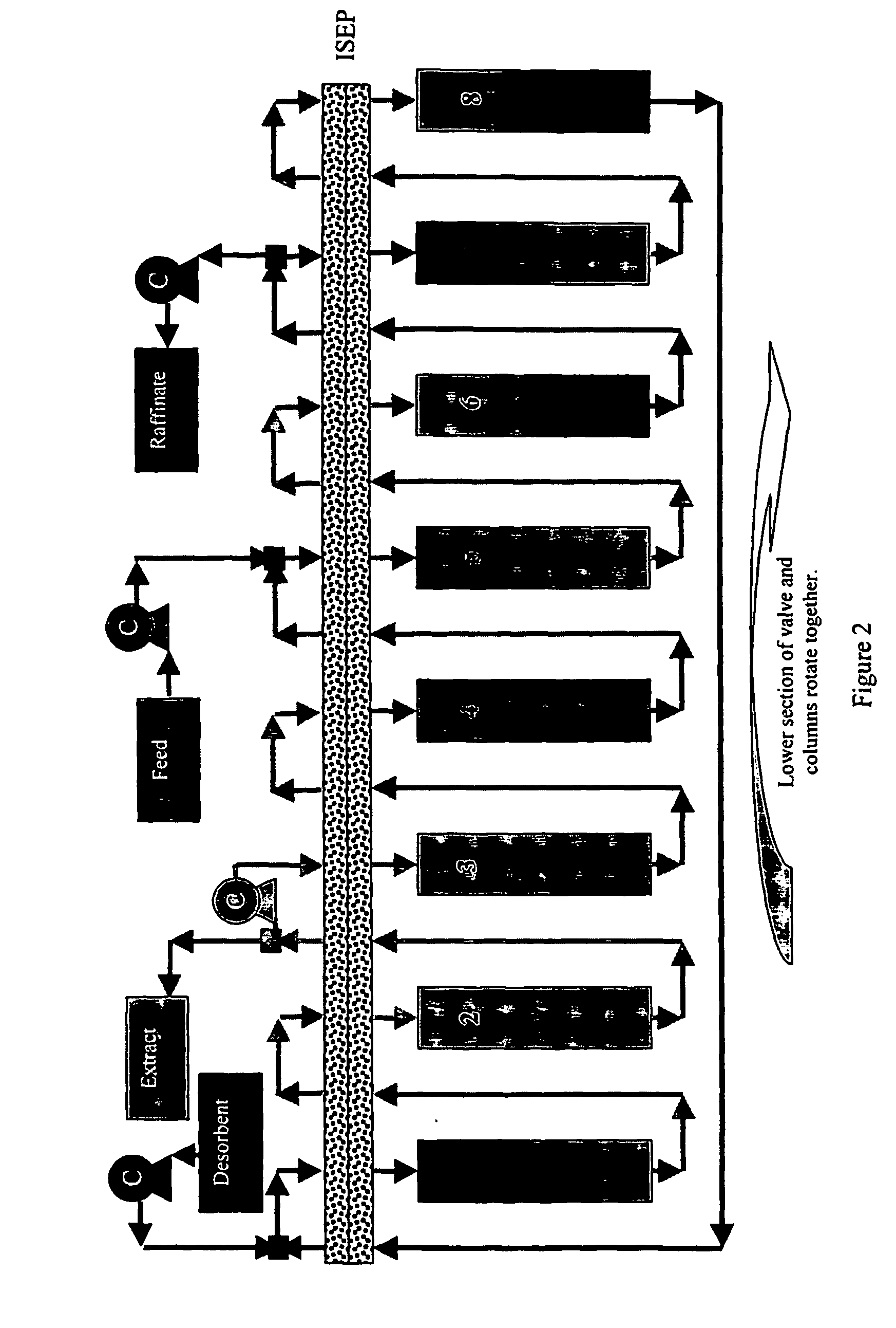
However, the system suffers from a number of drawbacks, including its high cost and the need to rotate the columns in operation.
Additionally, configurations supported by the ISEP valve are limited, and because the ISEP valve employs synchronous switching it cannot be used for variable zone length and online decoupled regeneration operation.
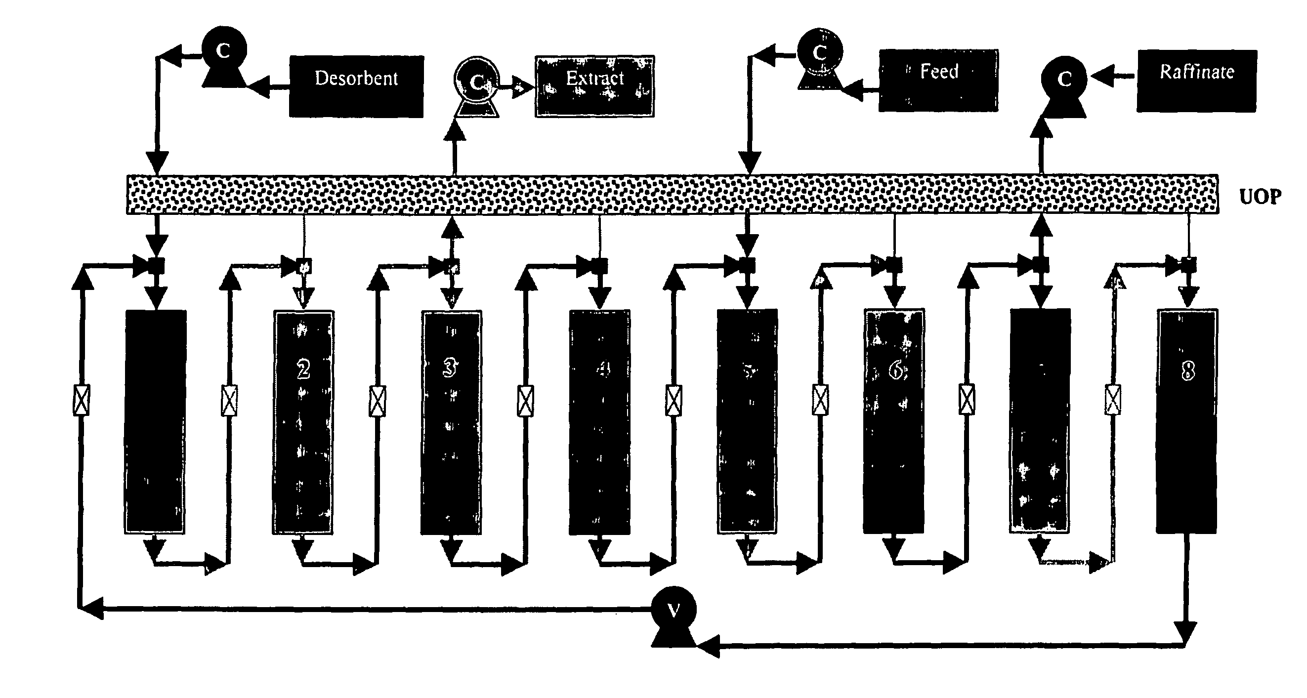
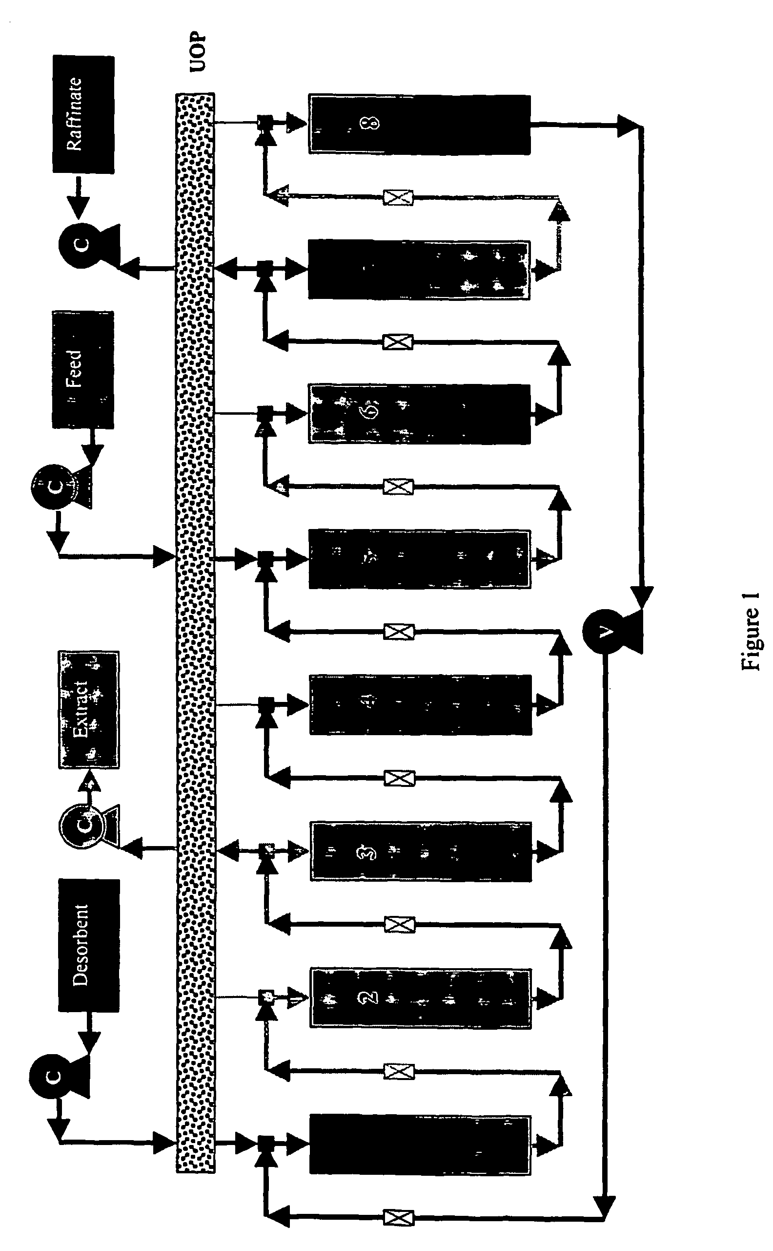
Multiple rotary valve systems use generic rotary valves such as the SD type (FIG. 3a) that are widely available and generally less expensive than their proprietary counterparts, though they typically have higher dead volume and more complex controls.
Nevertheless, while the design is efficient, it suffers from several significant drawbacks.
In particular, the admixing of the stagnant lines at every manifold causes significant contamination of the inlet and outlet streams.
The 1SD1C design suffers, however, from the fact that it requires a variable speed recycle pump and is limited to closed-loop binary separations.
On the other hand, on-off valves inherently have cross-contamination and the large number of valves employed in a on-off-based system requires complex controls.
However, the basic requirement of a transit line to the inline flow from the on-off valve remains, thus requiring a specialized flushing procedure which reduces yield, or a redesign of the on-off valve to merge with the tee, which defeats the purpose of using the lower cost generic valves.
Unfortunately, most SMB designs today are unable to handle periodic regeneration effectively.
However, this method requires the SMB system to pause while in operation, which results in unwanted spreading of the bands, and the labor-intensive operation is unattractive at best.
Because the length of time required to regenerate a column typically greatly exceeds the step time observed by the simulated moving bed, these systems typically require a large number of online columns in the regeneration zone.
The large number of columns reduces the average throughput per bed volume of the system and can rarely offset the benefit of coupling the regeneration step to the SMB separation steps.
However, its potential use is severely hindered by the need for valve systems that can accommodate such a process.

Method used


Image

  • Versatile simulated moving bed systems
  • Versatile simulated moving bed systems
  • Versatile simulated moving bed systems

Examples


example 1

Phenylalanine-Tryptophan SMB Separation--Experimental Setup and Design

[0185] The first experimental validation runs on the 1ST1C system used the well-understood phenylalanine-tryptophan as its model separation. Values from Xie, (2001) in Table 2 were used to design an appropriate set of operating parameters. The identical desorbent (water) and resin, (PVP) was used. The PVP resin, Reillex HP Polymer from Reilley Industries Inc. (Indianapolis, Ind.), is stable and easily regenerated. The resin was packed via the slurry packing method (Xie, (2001)). Table 3 lists the properties of the resin. The glass columns (30.5.times.2.68 cm) were obtained from Ace Glass Inc.

[0186] PVP resin was regenerated and repacked for Run 2. Water was pumped at high flow rates (>25 ml / min) through the columns for 24 hours before unpacking. The resin was successively soaked in 1 mol of NaOH, water, 1 mol of HCl, followed again by water, 50% ethanol by volume and finally with water again. Each step lasted 24 h...

example 2

Online Decoupled Regeneration

[0207] FIG. 46 illustrates a four column, four separation zone SMB with an additional column in an online decoupled regeneration zone. In this example, the regeneration step lasts for 9 regular step times. Between step 1 and 9, column 2 to 4 undergo conventional SMB switching. At the 10.sup.th switch, column 1 is switched from the regeneration zone into zone I, and column 2 from zone I into the regeneration zone. A column can be placed into the regeneration zone at regular or varying intervals, or triggered by the detection of fouling in the separation columns, or by other means. A corresponding number of columns need not be replaced when a regeneration switch occurs from the separation zone into the decoupled regeneration zones.

[0208] A mixture of sulfuric acid, xylose and sodium chloride was chosen as a model system to validate the online decoupled regeneration method. Xylose is the middle affinity product, sodium chloride the low affinity impurity and...


PUM

PropertyMeasurementUnit
Fractionaaaaaaaaaa
Fractionaaaaaaaaaa
Fractionaaaaaaaaaa

Abstract

Distributed valve simulated moving beds are described in which junctions located between successive columns interrupt the flow of process fluid between columns, and either transmit the process fluid through a zone bypass to a succeeding column within the same zone or, if the junction is located between zones, direct the process fluid to an input / output line that is dedicated to the particular zone that immediately follows the junction. At each step of the SMB's operation, the distribution of flows in each junction is modulated to accomplish movement of ports consistent with the SMB's design. Further described are simulated moving beds that contain one or more decoupled on-line regeneration zones. The regeneration zone is decoupled from the separation zones in the sense that it observes a step time (a "regeneration interval") that is different than the step time observed by the separation zones of the SMB. Because the regeneration zone is "on-line," the SMB need not be stopped to remove columns for regeneration. Because the regeneration zone is decoupled from the separation zones, the column can stay in the regeneration zone as long as needed to accomplish the regeneration, regardless of the step time observed by the SMB.

Description

REFERENCE TO PRIOR APPLICATIONS[0001] This application claims priority to U.S. Provisional Patent Application No. 60 / 325,688, filed Sep. 27, 2001, and U.S. Provisional Patent Application No. 60 / 333,725, filed Nov. 27, 2001.[0002] This invention relates to the separation of components in fluid streams using distributed valve simulated moving bed technology, and to simulated moving beds that contain on-line decoupled regeneration zones.[0003] Simulated moving beds have lately been the method of choice for separating highly demanding and expensive products such as pharmaceuticals, biochemicals and fragrances. The technology has moved from its roots in the petrochemical industry to sugar separations, and is now making successful inroads into the drug industry. Guest (1997); Juza (1999); Juza (2000). This technology has received particular attention for separating enantiomers with minute differences in adsorbent selectivity. Miller, et al. (1999).[0004] Chronologically, the first commerc...

Claims


Application Information

Patent Timeline
IPC IPC(8): B01D15/18B01D53/04B01D53/08
CPCB01D15/1842B01D53/0446B01D53/0454B01D53/08B01D2259/4067B01D2257/90B01D2259/40005B01D2259/40086B01D2215/023
Inventor CHIN, NIEN-HWA LINDACHIN, CHIM YONG
Owner PURDUE RES FOUND INC
Learn More