Cutting tool coated using PVD process

a technology of cutting tools and coatings, applied in the direction of manufacturing tools, natural mineral layered products, transportation and packaging, etc., can solve the problems of inability to use tools anymore, inability to reliably use ordinary coated indexable inserts as cutting tools for high-precision machining, and chipping of coatings

Inactive Publication Date: 2004-11-04
SUMITOMO ELECTRIC IND LTD
View PDF7 Cites 13 Cited by
  • Summary
  • Abstract
  • Description
  • Claims
  • Application Information

AI Technical Summary

Problems solved by technology

This condition tends to cause the coating to suffer chipping.
Once the chipping develops, the tool cannot be used anymore in many cases because the surface roughness increases or the amount of tool correction increases.
Therefore, an ordinary coated indexable insert cannot be used reliably as the cutting tool for the high-precision machining.
There is another problem.
When a sharp edge is covered with a highly hard TiAlN-based-coating, a high remaining compressional stress in the coating tends to spall the coating.
As a result, the coating suffer spalling even with a slight shock.
However, in the method of protecting the cutting edge with a built-up edge by forming a TiCN-based coating havi

Method used


Image

  • Cutting tool coated using PVD process
  • Cutting tool coated using PVD process
  • Cutting tool coated using PVD process

Examples


examples 1 to 12

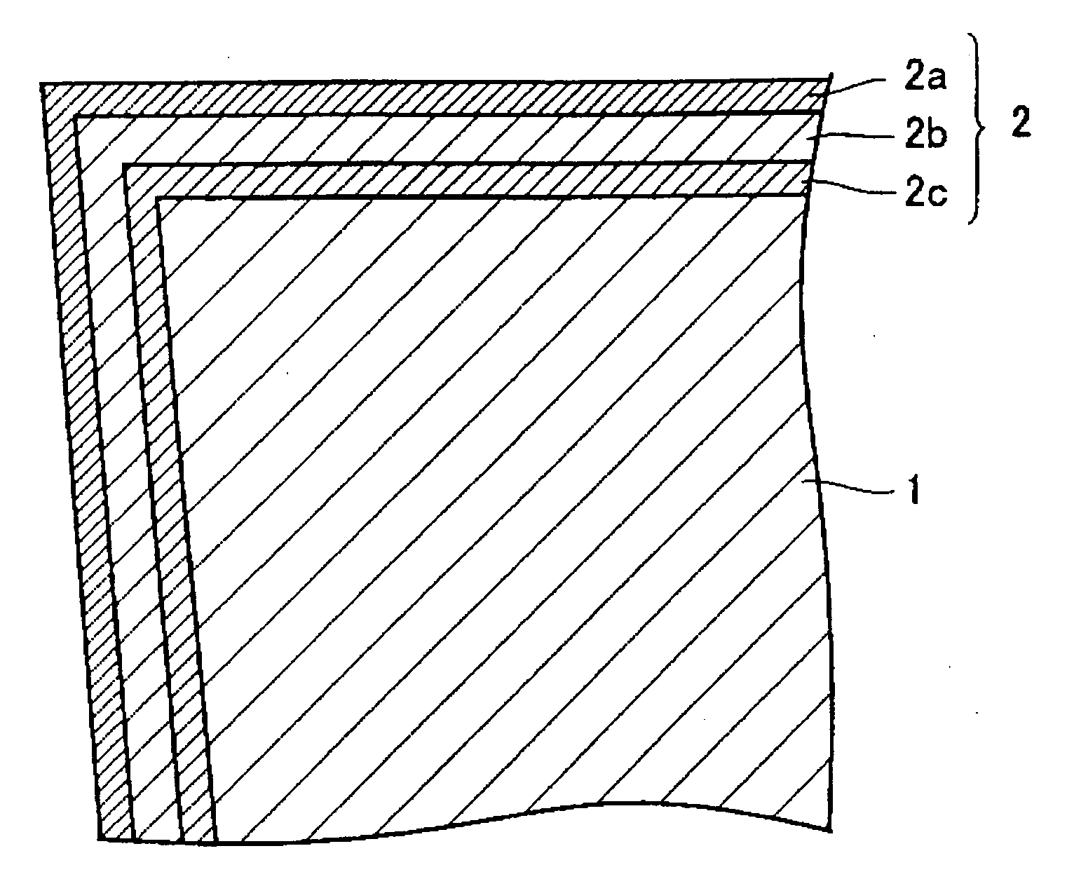
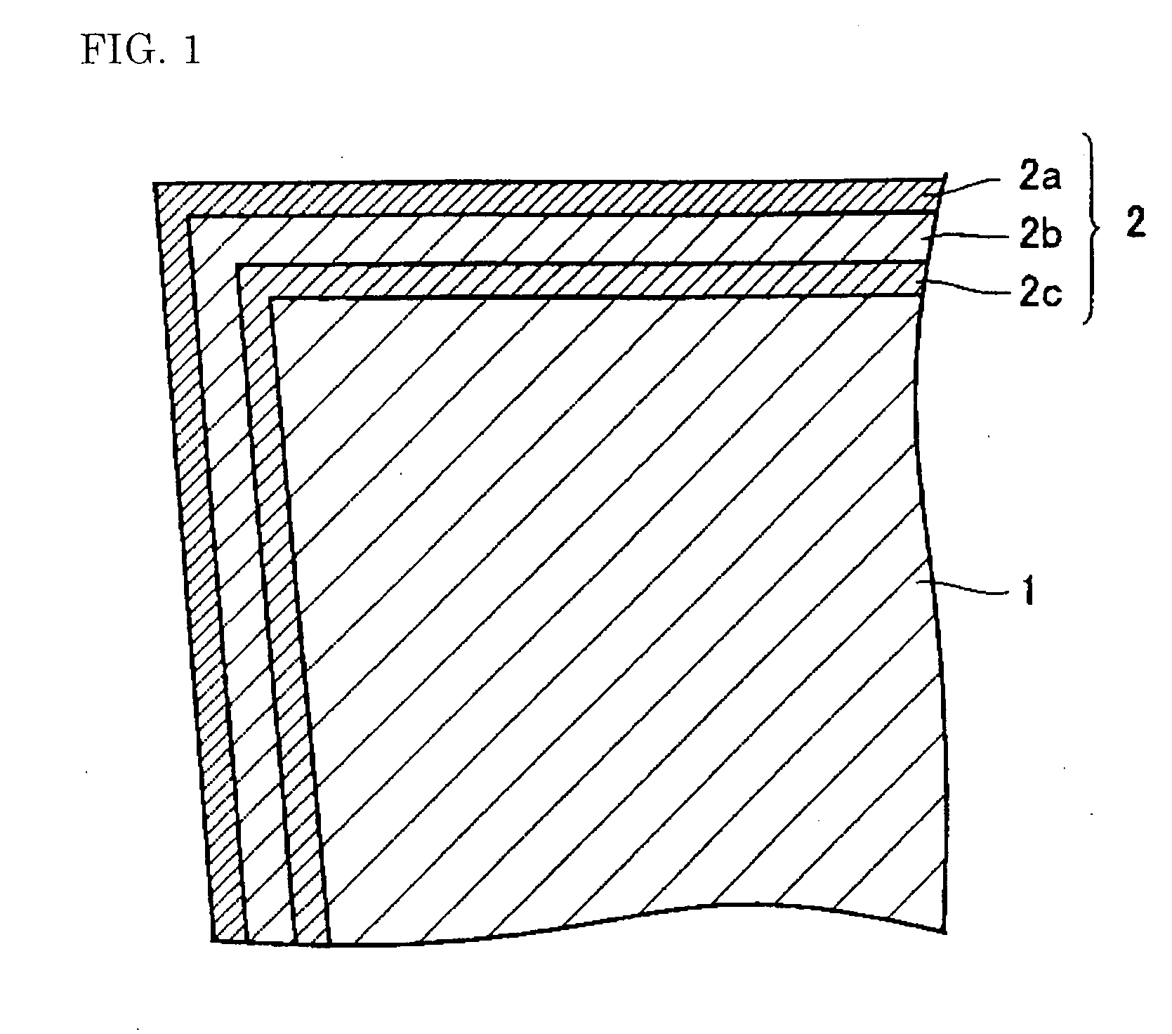
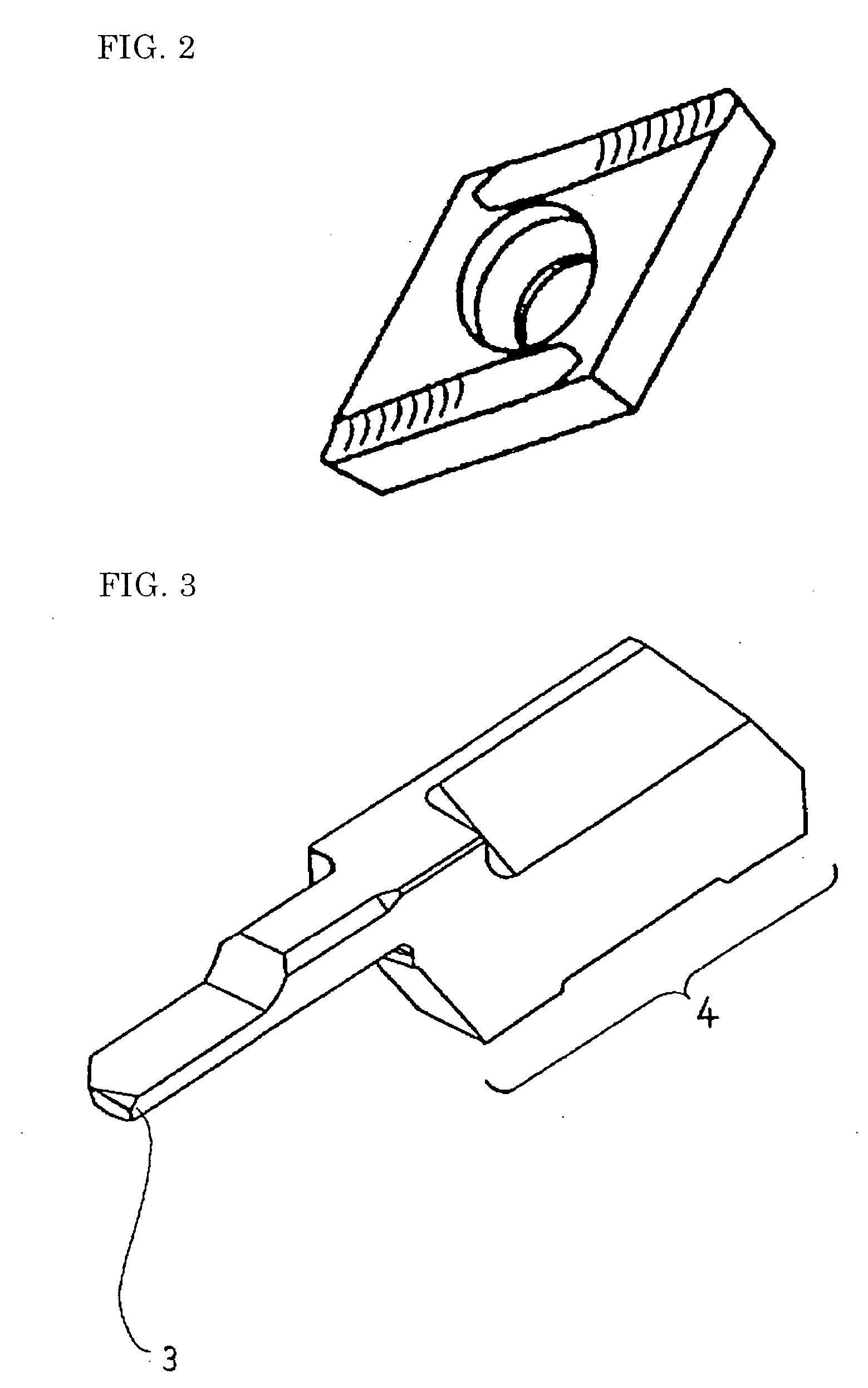
[0056] To prove the effect of the present invention, 12 types of samples were produced as Examples 1 to 12. The substrate used for the samples was cemented carbide which had WC having an average particle diameter of 1.0 .mu.m, which had a Co content of 10 wt. %, and which had a Vickers hardness of 15 GPa. By using the substrate, indexable inserts having the shape as shown in FIG. 2 were produced. The indexable insert had a diamond shape with a vertex angle of 55 degrees, had a flank with a clearance angle of 7 degrees, and had a rake face with a rake angle of 20 degrees. To perform high-precision machining, the polished substrate had a cutting part with an incisive sharp edge having a positive shape. The rake face and the flank had a surface roughness, Ra, of 0.2 .mu.m. Various coatings were used as shown in Table I. The coating was formed over the substrate using the arc ion-plating method, which is an ordinary method as the PVD process. The indexable insert was attached to an ordi...

examples 13 to 15

[0069] To confirm the effect of the cemented carbide as the substrate on the cutting performance, indexable inserts were produced by using the same procedure as used in Example 1, except for that the cemented carbides as shown in Table IV were used. The produced indexable inserts were subjected to the cutting of 1,000 work materials to evaluate the machined-surface quality and the dimensional variation. The results of the evaluation are also shown in Table IV. The evaluation method is the same as for Example 1.

4TABLE IV Machined-surface Dimensional quality variation Average (after (after Substrate particle Co Vickers cutting cutting (cemented diameter content hardness 1,000 1,000 carbide) (.mu.m) (wt %) (GPa) materials.) materials.) Example 13 0.5 5.0 21.5 .circleincircle. 7.1 Example 14 0.8 8.0 19.2 .circleincircle. 5.2 Example 15 1.3 12.0 15.2 .circleincircle. 6.2 Comparative 2.0 1.0 25.2 X 35.3 example 7 Comparative 2.0 8.0 14.3 X 45.2 example 8 Comparative 1.8 20.0 13.0 X 58.1 e...

examples 16 and 17

[0072] To confirm the effect of the cermet as the substrate on the cutting performance, indexable inserts were produced by using the same procedure as used in Example 1, except for that as the cermet, TiCN shown in Table V were used. The produced indexable inserts were subjected to the cutting of 1,000 work materials to evaluate the machined-surface quality and the dimensional variation. The results of the evaluation are also shown in Table V. The evaluation method is the same as for Example 1.

5TABLE V Machined-surface Dimensional quality variation Average (after (after particle Co Vickers cutting cutting Substrate diameter content hardness 1,000 1,000 (cermet) (.mu.m) (wt %) (GPa) materials.) materials.) Example 16 0.5 12.0 18.3 .circleincircle. 7.1 Example 17 1.3 8.0 17.2 .circleincircle. 5.2 Comparative 2.5 25.0 12.2 X 42.9 example 10

[0073] As can be seen from Table V, in Examples 16 and 17, a beautiful machined surface free from a whitish portion was obtained and the dimensional...


PUM

PropertyMeasurementUnit
Pressureaaaaaaaaaa
Pressureaaaaaaaaaa
Thicknessaaaaaaaaaa

Abstract

The present invention's cutting tool coated using the PVD process can cut with high geometrical precision, produce a good machined surface, and cut for a prolonged time. Its substrate is composed of cemented carbide or cermet, has a surface roughness, Ra, of at most 0.3 mum, is structured by hard particles having an average particle diameter of 0.3 to 1.5 mum, and has a cutting part having a sharp positive edge. Its coating is formed over the substrate using the PVD process and comprises an inner layer and an outer layer. The total thickness of the inner and outer layers is at most 2.0 mum. The inner layer comprises (a) at least one of the 4a-, 5a-, 6a-group elements, Al, and Si and (b) at least one of carbon, nitrogen, and oxygen. The outer layer comprises (c) at least one of boron, silicon, carbon, and nitrogen and (d) Ti.

Description

[0001] 1. Field of the Invention[0002] The present invention relates to a cutting tool coated using the physical vapor deposition (PVD) process that has excellent sharpness and can produce a product having a good machined surface and high geometrical precision, and particularly to a cutting tool coated using the PVD process to be used in a machining field that requires high precision, such as electronics parts.[0003] 2. Description of the Background Art[0004] Generally, the turning work for parts such as electronics parts, clock parts, and camera parts requires high precision in geometrical precision and in the surface roughness of a machined surface. In addition, the recent miniaturization of electronics and other devices has been requiring higher precision in geometrical precision and surface roughness for their parts. As the cutting tool for such high-precision parts, an indexable insert coated with TiAlN, TiCN, or a similar material has widely been used. An ordinary coated index...

Claims


Application Information

Patent Timeline
IPC IPC(8): B23B27/14B23C5/16C23C14/02C23C14/06C23C30/00
CPCC23C14/024Y10T428/25C23C30/005C23C14/028Y10T428/31663B23B27/14
Inventor IMAMURA, SHINYAMORIGUCHI, HIDEKIMURAKAMI, DAISUKE
Owner SUMITOMO ELECTRIC IND LTD
Why Eureka
Try Eureka