Solid electrolytic capacitor and method for producing the same

a technology of electrolytic capacitor and solid electrolytic capacitor, which is applied in the manufacture of electrolytic capacitors, variable capacitors, fixed capacitor details, etc., can solve the problems of increasing production costs, affecting the performance of capacitors, and firmly fixing tapes (films) to achieve good insulating properties, high heat resistance, and high heat resistance

Inactive Publication Date: 2004-11-25
MURATA MFG CO LTD
View PDF10 Cites 18 Cited by
  • Summary
  • Abstract
  • Description
  • Claims
  • Application Information

AI Technical Summary

Benefits of technology

0100] In the former case, the solution coated is thermally modified into a polymer and cured by a heat treatment at from 160 to 180.degree. C., as a result, a flexible film having high heat resistance and good insulating property is formed. The polyimide film obtained maintains rubber-like properties such that the tensile strength is 2.0 kg / mm.sup.2, the elongation of cured film is 65% and the initial elastic modulus is 40.6 kg / mm.sup.2, and at the same time exhibits high heat resistance such that the thermal decomposition temperature is 461.degree. C. Furthermore, the volume resistivity is as high as 10.sup.16 .OMEGA..multidot.cm even under humidification and the dielectric constant is as low as 3.2, thus the polyimide film holds excellent electrical properties as the insulating film.
0101] In the latter case, a film excellent in the heat resistance, mechanical properties, electrical properties and resistance against chemicals can be formed merely by removing the solvent at a temperature of 200.degree. C. or less. The film obtained has a tensile strength of about 11.8 kg / mm.sup.2, a cured film elongation of 14.2%, an initial elastic modulus of 274 kg / mm.sup.2 or more and a heat resistance such that the temperature for weight reduction of 5% is 515.degree. C. The volume resistivity is 10.sup.16 .OMEGA..multidot.cm and the dielectric constant is 3.1 (25.degree. C.) or 2.8 (200.degree. C.), thus, the film holds excellent electrical properties.
0102] In the present invention, the masking material solution may contain a defoaming agent (e.g., lower alcohol type, mineral oil type, silicone resins type, oleic acid, polypropylene glycol), a thixotropy-imparting agent (e.g., silica fine powder, mica, talc, calcium carbonate) or a silicon agent for resin modification (e.g., silane coupling agent, silicone oil, silicon-based surfactant, silicone-based synthetic lubricant). For example, by adding a silicone oil (e.g., polysiloxane) and a silane coupling agent, improvements may be expected in the defoaming property (to prevent bubbling at curing), releasability (to prevent adhering of electrically conducting polymer), lubricity (permeability inside the pore part), electrical insulating property (to prevent leakage current), water repellency (to prevent climbing up of the solution at the polymerization of electrically conducting polymer), damping and vibrationproofing property (to oppose pressure at the stacking of capacitor device), or heat resistance and weatherability of resin (introduction of crosslinking mechanism).

Problems solved by technology

The method of using phenol resins or epoxy resins as the masking material (JP-A-3-95910) is disadvantageous in that the capacitor is greatly damaged when pressed by external force, because the elastic modulus of resin is high and the stress against strains is high.
The method of forming a polyimide film by electro-deposition (JP-A-5-47611) may successfully form a film even inside the pore parts as compared with ordinary coating methods, however, the production cost increases because of necessity of the electrodeposition step and moreover, a dehydration step at a high temperature is necessary so as to form the polyimide film.
The method of forming an insulating resin-made tape or resin coating film part so as to prevent the solid electrolyte from climbing up at the manufacturing (JP-A-5-166681) has difficulty in firmly fixing the tape (film) at edge parts of the substrate and bears a risk of polymer solid electrolyte as the solid electrolyte invading the anode side.
As described above, the conventional masking means are insufficient and actually it has not been clear yet what is like the form (structure) of a masking that can insulate without fail the anode part from the cathode part of a solid electrolytic capacitor.

Method used


Image

  • Solid electrolytic capacitor and method for producing the same
  • Solid electrolytic capacitor and method for producing the same
  • Solid electrolytic capacitor and method for producing the same

Examples


example 2

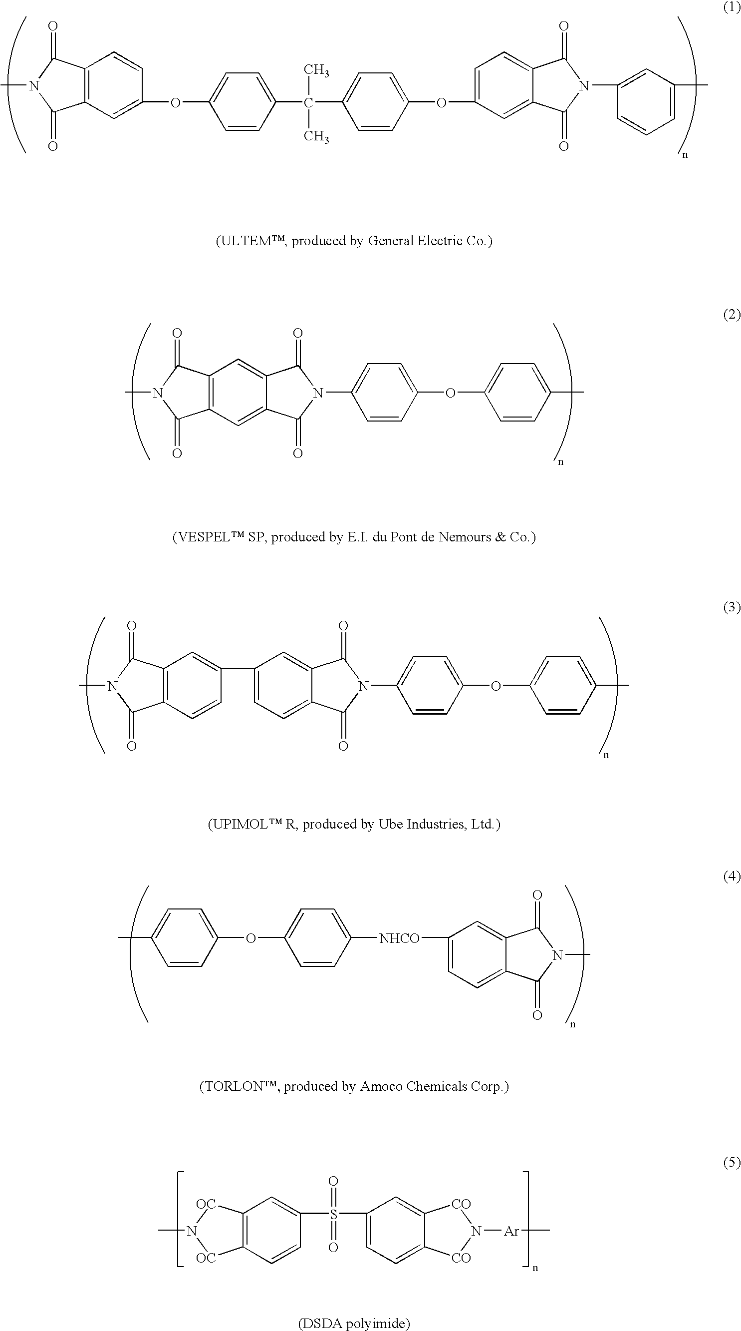
[0146] Chip-type solid electrolytic capacitors were manufactured in the same manner as in Example 1 except for using a polyimide resin solution (RIKACOAT.TM., produced by Shin Nippon Rika K. K.) as the masking material. The measurement of leakage current and the reflow soldering test were also performed in the same manner. The results obtained are shown in Table 1.

example 3

[0147] Chip-type solid electrolytic capacitors were manufactured in the same manner as in Example 1 except that the oxidative polymerization in the step of forming a solid electrolyte was performed by dipping the aluminum foil in an aqueous solution prepared by further adding sodium 2-anthraquinonesulfonate (produced by Tokyo Chemical Industry Co.) to Solution 2 to have a concentration of 0.07 wt %. The measurement of leakage current and the reflow soldering test were also performed in the same manner. The results obtained are shown in Table 1.

example 4

[0148] Chip-type solid electrolytic capacitors were manufactured in the same manner as in Example 1 except that the oxidative polymerization in the step of forming a solid electrolyte was performed by dipping the aluminum foil in an aqueous solution prepared by further adding sodium 2-naphthalenesulfonate (produced by Tokyo Chemical Industry Co.) to Solution 2 to have a concentration of 0.06 wt %. The measurement of leakage current and the reflow soldering test were also performed in the same manner. The results obtained are shown in Table 1.


PUM

PropertyMeasurementUnit
thicknessaaaaaaaaaa
thicknessaaaaaaaaaa
lengthaaaaaaaaaa

Abstract

The present invention relates to a solid electrolytic capacitor having a masking structure in which the insulation between the anode part and the cathode part can be ensured without fail, to its production method, to a method for coating a masking agent on a solid electrolytic capacitor substrate, and to apparatus therefore. According to the present invention, the masking material covers the dielectric film on the metal material having valve action and sufficiently infiltrates into the core metal made of a metal having valve action while the solid electrolyte is masked by the masking material without fail, so that a solid electrolytic capacitor can be produced that has a reduced leakage current and a reduced stress generated at the reflow treatment or the like.

Description

[0001] This application is a Divisional of application Ser. No. 09 / 576,957 filed May 24, 2000, which claims benefit of U.S. Provisional Application Nos. 60 / 135,843 and 60 / 135,844 filed on May 24, 1999; the disclosures of which are incorporated herein by reference in their entirety.[0002] The present invention relates to a solid electrolytic capacitor and to its production method. More specifically, the present invention relates to a solid electrolytic capacitor having a masking structure that in forming a solid electrolyte layer on a valve-acting metal substrate having thereon a dielectric film, in which a portion of metal substrate where the solid electrolyte layer is not provided (anode part) can be insulated without fail from the solid electrolyte layer or an electrically conducting layer formed on the solid electrolyte layer using an electrically conducting paste or the like (cathode part) and to its production method. Also, the present invention relates to a method and apparatu...

Claims


Application Information

Patent Timeline
Patent Type & Authority Applications(United States)
IPC IPC(8): H01G9/00H01G9/04H01G9/15
CPCH01G9/0029H01G9/04H01G9/15Y10T29/413Y02E60/13Y10T29/417H01G11/56
Inventor SAKAI, ATSUSHIMONDEN, RYUJINITOH, HIROSHIOKABE, TOSHIHIROFURUTA, YUJIOHATA, HIDEKISHIRANE, KORO
Owner MURATA MFG CO LTD
Why Eureka
Try Eureka