Organic luminescent compounds and methods of making and using same

a luminescent compound and organic technology, applied in the direction of discharge tube luminescnet screens, thermoelectric devices, natural mineral layered products, etc., can solve the problems of lack of long-term stability in oleds, gradual deterioration of color purity of display, and many challenges to be addressed. , to achieve the effect of improving contact, improving contact, and improving conta

Inactive Publication Date: 2004-12-30
QUEENS UNIV OF KINGSTON
View PDF3 Cites 13 Cited by
  • Summary
  • Abstract
  • Description
  • Claims
  • Application Information

AI Technical Summary

Benefits of technology

[0077] FIG. 13 shows the dependence of Luminance (L) and Current Density (J) on Voltage (V) of a film of compound (4) in a two layer EL device of the following configuration: ITO / NPB (40 nm) / compound(4) (40 nm) / LiF (1 nm) / Al, where NPB is the hole transport layer, compound (4) is both the emitter and electron transport layer and LiF is added to improve contact between the electron transport layer and the cathode.
[0156] Organic semiconducting materials can be used in the manufacture of photovoltaic cells that harvest light by photoinduced charge separation. To realize an efficient photovoltaic device, a large interfacial area at which effective dissociation of excitons occurs must be created; thus an electron donor material is mixed with an electron acceptor material. (Here, an exciton is a mobile combination of an electron and a hole in an excited crystal, e.g., a semiconductor.) Organic luminescent compounds as semiconductors are advantageous due to their long lifetime, efficiency, low operating voltage and low cost.

Problems solved by technology

However, several challenges still must be addressed before OLEDs become truly affordable and attractive replacements for liquid crystal based displays.
A common problem with blue emitters is their lack of long term stability in OLEDs.
OLEDs generally suffer from a gradual intensity decrease of the blue hue, which results in gradual deterioration of the color purity of the display, and ultimately failure of the device.
Even this modest expectation is a big challenge for currently available OLEDs.
There are several blue luminescent inorganic coordination compounds known (U.S. Pat. No. 6,500,569, U.S. Pat. No. 6,312,835, Yang, 2001, Jia et al., 2003); however, in some cases, due to a propensity for oxidation and / or hydrolysis reactions, such complexes are not very stable in solution.
One family of known inorganic blue emitters, lanthanide ions, have low emission efficiency and require the use of a host (generally an inorganic salt), which makes it difficult to process them into thin films.
Many of these have poor luminescence efficiency and poor stability.
Even the best blue emitters currently available do not have the long term stability desired for commercial devices.
The limitations discussed above could restrict the market for OLED products, despite their many superior aspects as compared with liquid crystal displays.

Method used


Image

  • Organic luminescent compounds and methods of making and using same
  • Organic luminescent compounds and methods of making and using same
  • Organic luminescent compounds and methods of making and using same

Examples


working examples

[0163] All starting materials were purchased from Aldrich Chemical Company and used without further purification. Solvents were freshly distilled over appropriate drying reagents. All experiments were carried out under a dry nitrogen atmosphere using standard Schlenk Techniques unless otherwise stated Thin Layer Chromatography was carried out on SiO.sub.2 (silica gel F254, Whatman). Flash chromatography was carried out on silica (silica gel 60, 70-230 mesh). .sup.1H and .sup.13C spectra were recorded on a Bruker Avance 300 spectrometer operating at 300 and 75.3 MHz respectively. Excitation and emission spectra were recorded on a Photon Technologies International QuantaMaster Model 2 spectrometer. Spin coating was done on Chemat Technology spin-coater KW-4A and vacuum deposition using a modified Edwards manual diffusion pump. The EL spectra for compound (3) (see FIG. 8) were taken using Ocean Optics HR2000 and all data involving current, voltage and luminosity using a Keithley 238 hi...

example 1

1-pyrenyl-2, 2 dipyridylamine (2)

[0164] The mixture of 0.145 g, 1-bromopyrene (0.5 mmol), 0.10 g 2,2 dipyridylamine (0.58 mmol), 0.125 g CuI, 0.235 g K.sub.3PO.sub.4, 0.033 mL 1,2-transdiaminocyclohexane and 1 mL 1,4-dioxane was stirred at 110.degree. C. for 24 hours. After cooling to room temperature, the mixture was extracted with dichloromethane (3.times.15 mL). The solvent was evaporated under reduced pressure. The residue was subjected to column chromatography on silica gel (CH.sub.3COOEt / Hexane, 2:1) to afford a white compound (2) in 39% yield. The molecular structure of (2) was confirmed by X-ray crystallography, the structure is pictured in FIG. 9. .sup.1H NMR in CD.sub.2Cl.sub.2 at 25.degree. C.: .delta. ppm=8.31(d, J=8.1, 1H), 8.27(m, 3H), 8.19 (m, 3H), 8.06(m, 3H), 7.95 (d, J=8.1, 1H), 7.56 (m, 2H), 7.08(td, d=8.4, 0.9, 2H), 6.94(ddd, J=7.2, 4.8, 1H). .sup.13C NMR in CD.sub.2Cl.sub.2 at 25.degree. C., 6 ppm: 159.08, 148.72, 139.16, 137.94, 131.81, 131.62, 131.12, 129.65, ...

example 2

Synthesis of 4-(1-pyrenyl)phenyl-2.2'-dipyridylamine (3)

[0165] A mixture of 1-bromopyrene (0.5 g, 1.78 mmol), Pd(PPh.sub.3).sub.4 (0.062 g, 0.054 mmol) and toluene(40 mL) was stirred for 10 minutes under N.sub.2(g). A solution of p-(2,2'-dipyridylamino)phenylboronic acid (0.57 g, 1.96 mmol) in 20 mL EtOH and a solution of NaOH (0.8 g) in 20 mL H.sub.2O were added. The resulting mixture was heated and stirred at reflux for 24 hours and was then allowed to cool to room temperature. The water layer was separated and extracted with methylene chloride (CH.sub.2Cl.sub.2) (3.times.15 mL). The combined organic layers were dried over MgSO.sub.4, and evaporated under reduced pressure. Purification of the crude product was performed by column chromatography (THF:Hexane, 3:2) and afforded (3) as a white solid in 83% yield. The molecular structure of (3) was confirmed by X-ray crystallography, the structure is pictured in FIG. 10. .sup.1H NMR in CD.sub.2Cl.sub.2 at 25.degree. C.: .delta. ppm=8.4...


PUM

PropertyMeasurementUnit
temperatureaaaaaaaaaa
thickaaaaaaaaaa
thicknessaaaaaaaaaa

Abstract

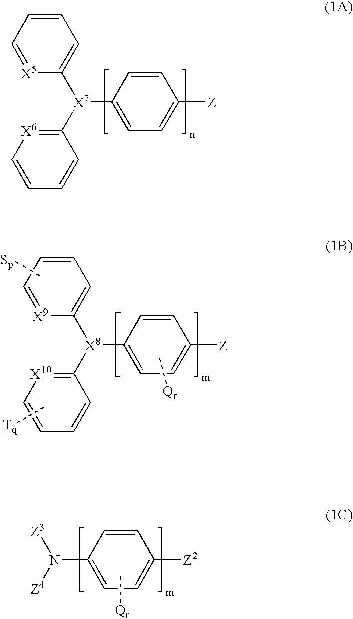
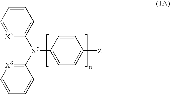
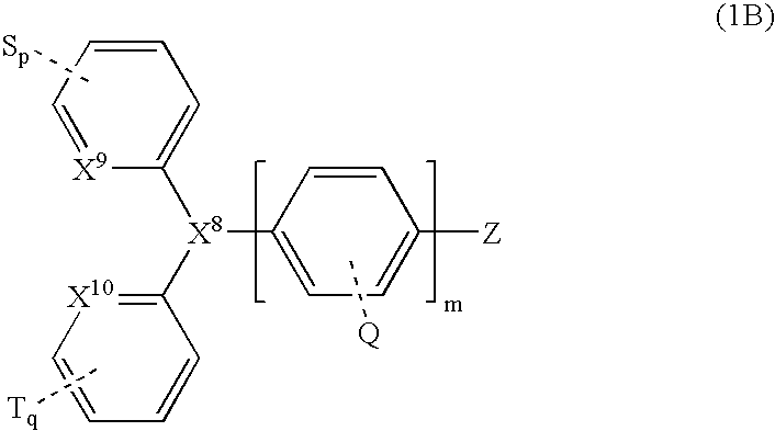
The invention provides organic compounds of the general structure (1) (see formula 1) that are photoluminescent and electroluminescent, emitting intense blue ligh t. The invention further provides methods of synthesizing such compounds, methods of producing photoluminescence and electroluminescence, methods of applying the compounds in thin films, and us es of the compounds of the invention in luminescent probes, electroluminescent displays and as p H probes and metal ion detectors.

Description

[0001] This application claims the benefit of priority from U.S. Provisional Application Ser. No. 60 / 463,336, filed Apr. 17, 2003, which is herein incorporated by reference in its entirety.[0002] The invention relates to organic compounds having luminescent properties, and to methods of synthesizing and using such compounds. The invention more particularly relates to compounds having photoluminescent and / or electroluminescent properties, and to synthesis and uses of same. The invention also relates to compounds having photo-receptor properties due to their ability to separate charges. The invention also relates to compounds having photon harvesting properties. The invention also relates to compounds that visibly display detection of metal ions or acid. The invention further relates to compounds that can provide a molecular switch.[0003] Production of devices based on electroluminescent display is a rapidly growing, billion dollar industry. Bright and efficient organic light-emitting...

Claims


Application Information

Patent Timeline
Patent Type & Authority Applications(United States)
IPC IPC(8): C07D213/74C09K11/06H01L51/00H01L51/50H05B33/14
CPCC07D213/74C09K11/06C09K2211/1007C09K2211/1011C09K2211/1014C09K2211/1029C09K2211/1044H01L51/0052H01L51/0054H01L51/0059H01L51/006H01L51/0061H01L51/0067H01L51/5012H01L51/5048H01L2251/308H05B33/14Y02E10/549H10K85/622H10K85/615H10K85/631H10K85/636H10K85/633H10K85/654H10K50/14H10K50/11H10K2102/103
Inventor WANG, SUNINGJIA, WEN-LI
Owner QUEENS UNIV OF KINGSTON
Why Eureka
Try Eureka