Non-sintered type thin electrode for battery, battery using same and process for same

a thin electrode, non-sintered technology, applied in the direction of cell components, electrochemical generators, transportation and packaging, etc., can solve the problems of low mechanical strength, low mechanical strength, and low mechanical strength of the entire electrode, so as to prevent the peeling of the active material layer, the effect of enhancing the active material powder

Inactive Publication Date: 2005-01-27
THE UNIV OF QUEENSLAND
View PDF12 Cites 162 Cited by
  • Summary
  • Abstract
  • Description
  • Claims
  • Application Information

AI Technical Summary

Benefits of technology

[0026] (d) Preventing the peeling of the active material powders layer from the substrate through the spirally winding process of the electrode and also the shedding of active material powders that formed the electrode through the repetitive charging and discharging afterwards, by bending the walls of the concave and convex hollow parts into one direction specifically in the vicinity of the edge, just as to wrap the space between the concave and the next concave or the convex and the next convex in order to prevent the shedding of the active material powders.
[0027] In addition, by maintaining all the active material powder, within 150 μm in the distance from the nearest conductive electrode substrate, the charging and discharging reaction, particularly the high rate discharge reaction, of the active material powder is enhanced and by using a cylindrical battery case wherein a ratio (t2/t1) of the thickness (t2) of the bottom to the thickness (t1) of the side walls is 1.5 or more, that is to say, by using a cas

Problems solved by technology

In general, the former exhibits excellent characteristics in electronic conductivity (high-rate charge and discharge characteristics) due to a large amount of metal used in the sintered plaque and has a long cycle-life with excellent mechanical strength and stability in the shedding of active material, while it has the defect that the electrode is heavy and has a small volumetric energy density due to a small amount of active material impregnated therein because of a large volume of the electrode substrate.
On the contrary, a representative and simple non-sintered type electrode is inexpensive and light weight, and has a large volumetric energy density because of using an inexpensive substrate of a small volumetric amount in the electrode, which is easy to manufacture, through the coating or direct filling process of active material powder, while it entails the problem that the entire electrode is inferior in current collection ability as a whole, in the mechanical strength and in the holding of the active material.
These are significant problems in secondary batteries where charging and discharging is repeated and, therefore, a variety of ideas are incorporated into respective battery systems.
However, though these types of electrodes have a high capacity and a high reliability and are easily made to have higher capacity and to be lighter weight compared with the sintered type, due to a small amount of metal employed in the substrate, they have the technical problems that the mechanical strength is low and the electronic conduction of the entire electrode is inferior due to a large pore diameter within the substrate and, in addition, have the technical problem that the cost of the substrate is high.
As for the structure of this nickel positive electrode for a mass-production level, the non-sintered type was limited only to the pocket type, due to the electrode mechanical stability.
Though a light weight nickel posit

Method used


Image

  • Non-sintered type thin electrode for battery, battery using same and process for same
  • Non-sintered type thin electrode for battery, battery using same and process for same
  • Non-sintered type thin electrode for battery, battery using same and process for same

Examples


embodiments

[0072] Next, a concrete embodiment of the present invention is described.

production example

[0073] As shown in FIG. 10, a nickel plated steel plate (plating thickness of 1 μm) having a thickness of 0.3 mm,which is punched out into a circle, is submitted to one cycle of ironing with drawing by spindle 13 in the manner known in the art so as to form a cylindrical container 14 with a bottom. More concretely, as for the dimensions the outer diameter is 14 mm, the thickness of the side walls is 0.16 mm and the thickness of the bottom is 0.25 mm. Here, it is preferable to provide thicker parts R at the border part of the inside of the case between the side walls and the bottom, in order to prevent the physical strength of the border from being weakened.

embodiment 1

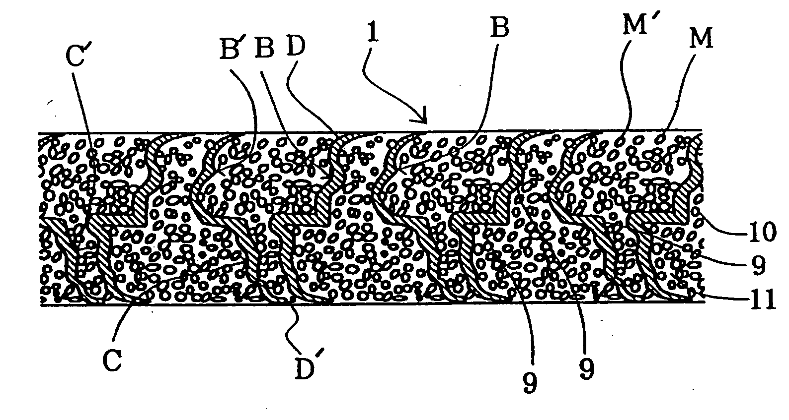
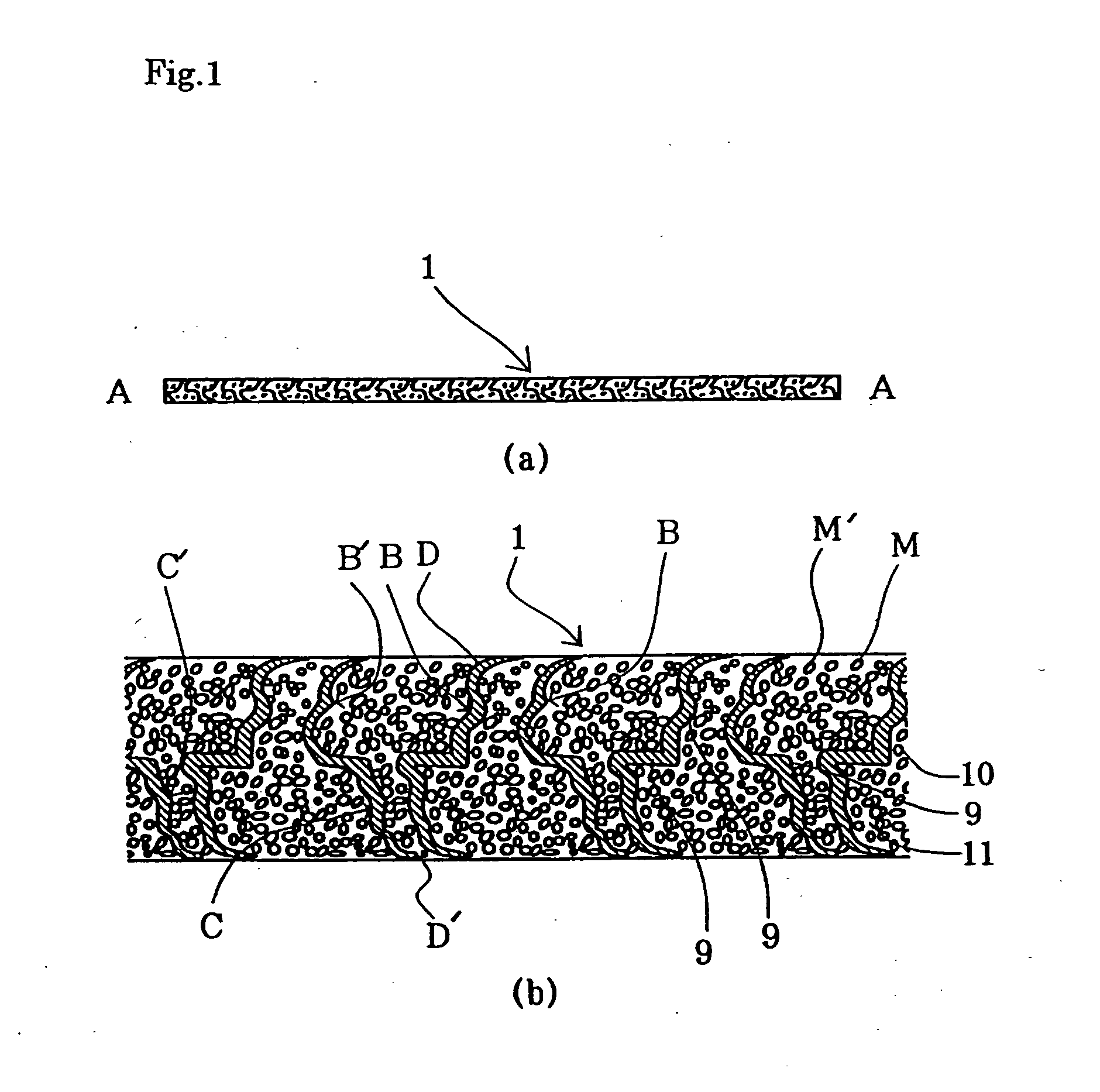
[0074] Nickel foil in a wide belt-like form, having a thickness of 30 μm, is pressed between a pair of dies (or between rollers) wherein innumerable microscopic conical concavities and convexities are formed on the surface of the both dies so that a three dimensional conductive electrode substrate having innumerable microscopic hollow chimney shapes in the nickel electrode substrate 9 of FIG. 4 is manufactured. Two examples of the possible kinds of patterns of the concave and convex parts of the nickel substrate 9 in FIG. 4 are shown in FIGS. 5(a) and 5(b) which are the partially enlarged figures of the nickel electrode substrate, wherein parts B and C in FIG. 5 indicate the convex parts and the concave parts, respectively. The closest parts to the convex parts (concave parts) in FIG. 5(a) are all concave parts (convex parts) and in FIG. 5(b) the closest parts to the convex parts (concave parts) are concave parts (convex parts) in a ration of four out of six. In the present embodime...


PUM

PropertyMeasurementUnit
Angleaaaaaaaaaa
Thicknessaaaaaaaaaa
Pressureaaaaaaaaaa

Abstract

An electrode substrate is formed by mechanically processing a nickel foil so as to be made three dimensional through the creation of concave and convex parts, and then, this substrate is filled with active material or the like so that an electrode is manufactured, wherein the above described concave and convex parts are rolling pressed so as to incline in one direction. Furthermore, an electrode for secondary battery is formed by using the above described method.

Description

FIELD OF INVENTION [0001] The present invention relates to a paste type thin electrode for a battery, in which the cost is reduced and the high rate discharge characteristics and the cycle life are improved, and to a secondary battery using this electrode. BACKGROUND OF THE INVENTION [0002] At present electrodes for batteries, used commercially for secondary batteries, are broadly categorized as sintered type electrodes and non-sintered type electrodes. In the sintered type electrodes, active material is filled into a highly porous three dimensional substrate where metal powder is sintered to have a large porosity on both sides of a two dimensional metal substrate. In the non-sintered type electrodes, the active material powder with a binder is coated on a two dimensional metal substrate or grid, or filled into a three dimensional substrate, such as foamed nickel, metal bag or tube, without employing a sintered substrate. [0003] In general, the former exhibits excellent characterist...

Claims


Application Information

Patent Timeline
IPC IPC(8): C25D3/12H01M4/02H01M4/04H01M4/139H01M4/24H01M4/32H01M4/62H01M4/66H01M4/70H01M4/72H01M4/74H01M4/78H01M4/80H01M6/10H01M10/052H01M10/34
CPCH01M4/0404Y10T29/49115H01M4/242H01M4/32H01M4/622H01M4/661H01M4/663H01M4/667H01M4/74H01M4/745H01M6/10H01M10/052H01M10/345H01M2004/021Y02E60/124Y02T10/7011Y02E60/122Y10T29/10H01M4/0409Y02E60/10
Inventor MATSUMOTO, ISAO
Owner THE UNIV OF QUEENSLAND
Why Eureka
Try Eureka