
Substrate for optical element, organic electroluminescence element and organic electroluminescence display device

a technology of organic electroluminescence and substrate, which is applied in the direction of discharge tube luminescnet screens, identification means, instruments, etc., can solve the problems of the lumonous efficiency is above the limit, and it is difficult to form a lens for light-focusing properties. , to achieve the effect of improving the light extraction efficiency of an organic electroluminescence element, improving the luminance of the organic electroluminescence element, and improving the light extraction efficiency

Active Publication Date: 2005-02-03
SAMSUNG DISPLAY CO LTD
View PDF3 Cites 45 Cited by
  • Summary
  • Abstract
  • Description
  • Claims
  • Application Information

AI Technical Summary

Benefits of technology

The present invention is contrived to figure out how emitting light having an angle more than a critical angle and totally reflected at the air / glass interface can be effectively scattered to emit at an angle less than the critical angle.
The present invention provides an optical element substrate (light emitting device substrate) that improves light extraction efficiency of an organic electroluminescence element.
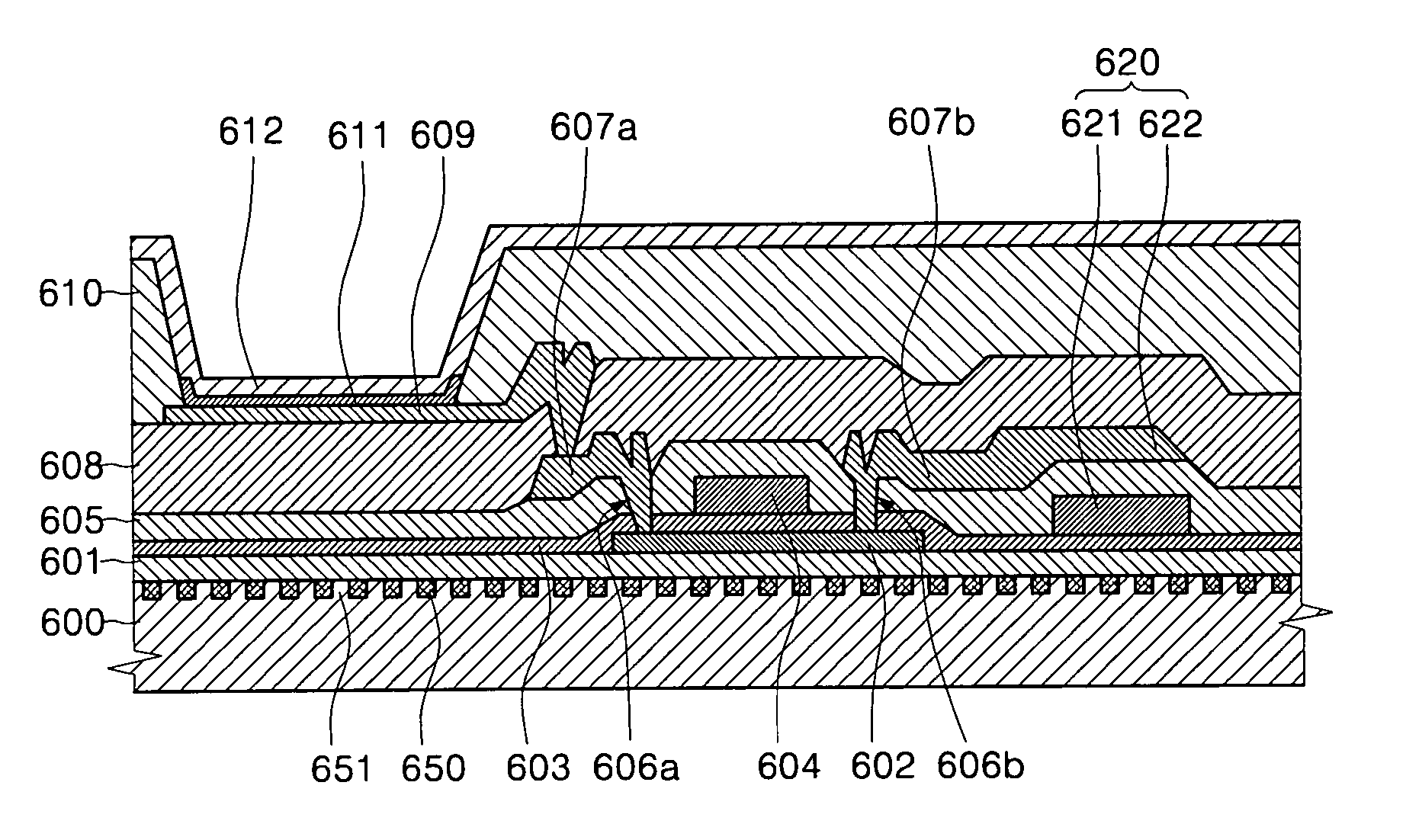
After reviewing the foregoing, the inventors found that light extraction efficiency is improved by using a substrate for an optical element comprising a light scattering unit that scatters visible light and a light transmissive opening that transmits the visible light in the light transparent substrate that transmits the visible light, as a light extraction substrate of an organic electroluminescence element. With this substrate for the optical element, a luminance of the organic electroluminescence element is increased.

Problems solved by technology

However, the organic electroluminescence has a limit to the probability of forming a singlet due to dependency of spin statistics when recombining carriers, and thus having an upper limit in lumonous efficiency.
In an organic electroluminescence element having a strong limitation in luminous efficiency, light extraction efficiency undergoes fatal performance degradation.
The method for increasing light extraction efficiency by making the substrate have a light-focusing property or the method of forming a reflective surface on a side of the device is effective for a device with a large luminous area, however, in a device with a small pixel area such as a dot matrix display, it is difficult to form a lens for light-focusing property or the reflective surface on a side, etc.,.
Further, in the organic electroluminescence element, a film thickness of an emission layer is below several μm, so that it is difficult to perform taper turning to form a reflective mirror on a side of a device with the current processing technology for fine, thereby significantly increasing cost.
Meanwhile, a method of introducing the flat layer having an intermediate refractive index between a substrate glass and a luminous body to form an anti-reflection layer has an effect in improving light extraction efficiency, however, it is difficult to prevent total reflection with this method.
Therefore, while the effect of increasing light extraction efficiency is valid for the inorganic electroluminescence having a large refractive index, it is not valid for the organic electroluminescence element having a small refractive index.
Further, transmission light toward a metal electrode (cathode) surface in the organic electroluminescence layer has great transmission loss due to the metal electrode.
Further, while Japanese Patent Application Laid-Open No. 2002-260845 describes that the performance is improved when the light angle changing means are distributed all over the substrate (FIG. 10 and Paragraph 0032 in the Description corresponding to FIG. 10 in this publication), however, there is a problem that if a plurality of scatters exist in the thickness is direction, the substrate becomes white, thus reducing the color purity of the emitted light.
As described above, the light extraction of the organic electroluminescence is still insufficient.

Method used


Image

  • Substrate for optical element, organic electroluminescence element and organic electroluminescence display device
  • Substrate for optical element, organic electroluminescence element and organic electroluminescence display device
  • Substrate for optical element, organic electroluminescence element and organic electroluminescence display device

Examples


example 1

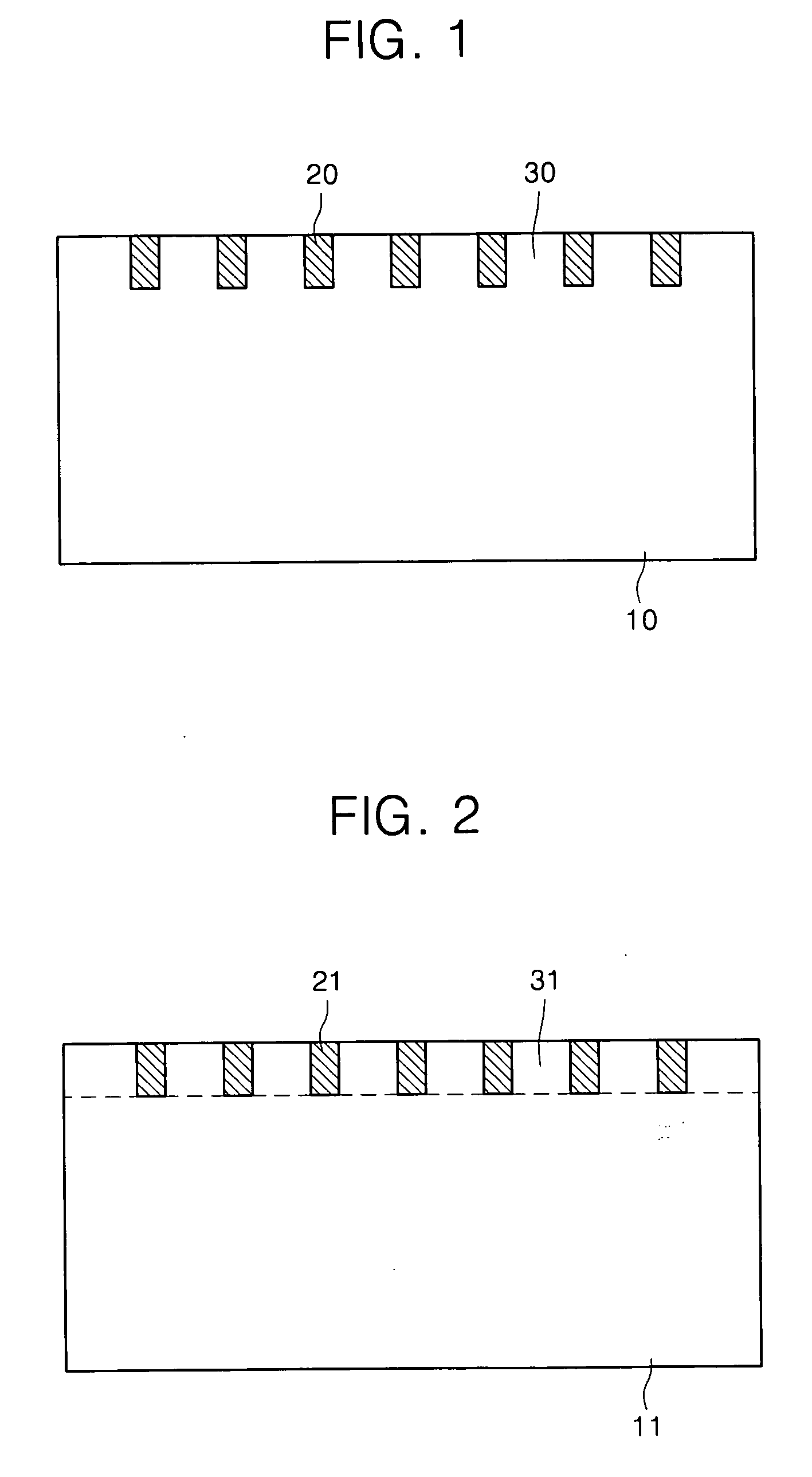
A positive resist material was formed on the quartz substrate (refractive index: 1.457) in a thickness of 4000 μm using a spin coater, as a photoresist material, and then the resist material was patterned using a photomask.

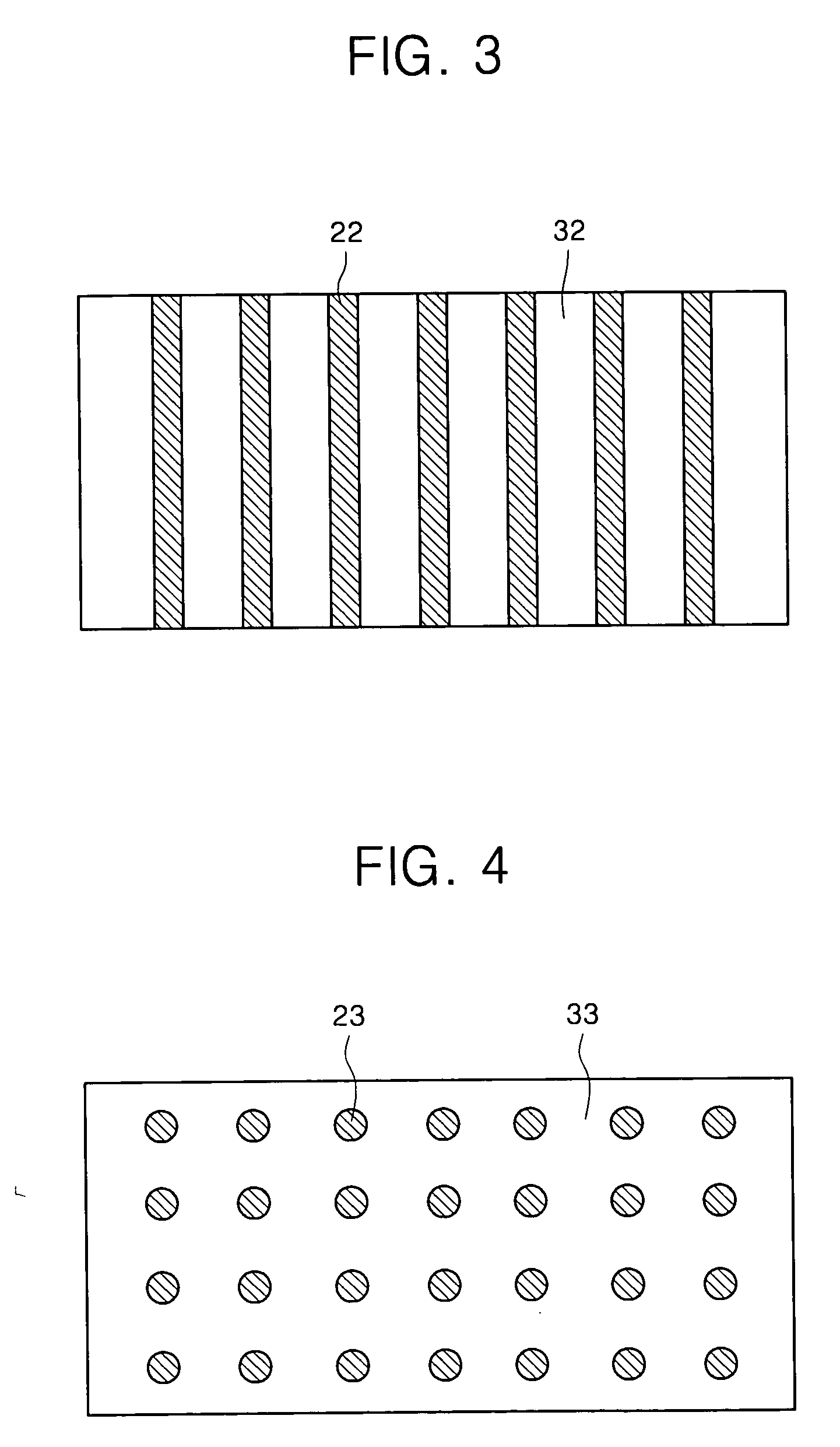
As a light source, an Hg-Xe lamp (wavelength: 250 nm) was used. Here, a stripe type mask pattern was used with a period of 1.0 μm, a line width of 0.75 μm, and a space width of 0.25 μm. With this mask, after exposed one time, the mask was rotated 90°, and was exposed again with the same condition. After such exposure, the mask was processed with alkali developer to form the resist pattern. As a result of SEM observation, it was confirmed that a target grating pattern could be manufactured. The quartz substrate attached to the manufactured resist pattern was etched by reactive gas etching (Samuco, RIE1ONR). Etching was performed under the condition of 100W output, using CF4(4Pa, 20 SCCM). The etching was performed to make a groove of 10000 μm in the quartz subst...

example 2

A positive resist material was formed on the quartz substrate (refractive index: 1.457) in a thickness of 4000□ by a spin coater, as a photoresist material, and then the formed photoresist layer was exposed by two-optical-flux laser interference exposure system. As a laser light source used in this two-optical-flux laser interference exposure, an Ar-ion laser (wavelength: 488 nm) was employed to make exposure under the following conditions.

Laser light was branched into 2 light flux with a beam splitter, and interference exposure was performed with a mirror such that a crossing angle becomes about 31 degree on the substrate surface (laser illumination intensity: 100 mA / μm, exposure time: 15 seconds). After such exposure was performed one time, the substrate was rotated 90° and exposed again with the same condition.

After exposure, it was processed by alkali developer AZ300MIF (manufactured by Clariant Japan Co.) to form the grating pattern. As a result of SEM observation, the per...


PUM


Abstract

The present invention uses a substrate for an optical element comprising a light scattering unit that scatters visible light, and a light transmissive opening that transmits the visible light in a light transparent substrate transmitting the visible light, as a light extraction substrate of the organic electroluminescence element. With this, a substrate for an optical element, an organic electroluminescence element, and an organic electroluminescence display device are provided that improves the light extraction efficiency to outside of the substrate and also improves the light extraction efficiency by obtaining a high luminance organic electroluminescence element.

Description

CROSS-REFERENCE TO RELATED APPLICATION This application claims the benefit of Japanese Patent Application No. 2003-282202, filed Jul. 29, 2003, the disclosure of which is hereby incorporated herein by reference in its entirety. BACKGROUND OF THE INVENTION 1. Field of the Invention The present invention relates to a substrate for an optical element that emits light of a specific wavelength range by current driving, optical element using the same and organic electroluminescence display device used as a display device. 2. Description of the Related Art 1 An organic electroluminescence (organic EL) device is an emissive device using a principle that a fluorescent material is emitted by recombination energy between holes injected from an anode and electrons injected from a cathode by applying the electric field. Since C. W. Tang, et al. reported a low voltage driven organic electroluminescence display with a stacked type device (C. W. Tang, S. A. VanSlyke, Applied Physics Letter, Vol...

Claims


Application Information

Patent Timeline
Patent Type & Authority Applications(United States)
IPC IPC(8): H05B33/02G09F9/30H01J1/62H01J63/04H05B33/12H05B33/14H05B33/22H10K99/00
CPCH01L27/3244H01L51/0096Y02E10/549H01L51/5268H01L51/5262H10K59/12H10K77/10H10K59/877A22C25/22A22C25/08A22C25/003H10K50/85H10K50/854
Inventor GOTOH, TOMOHISATOGUCHI, SATORUKAMIJO, ATSUSHIONISHI, YASUHARUISHIKAWA, HITOSHIYAMANARI, JUNICHI
Owner SAMSUNG DISPLAY CO LTD
Learn More