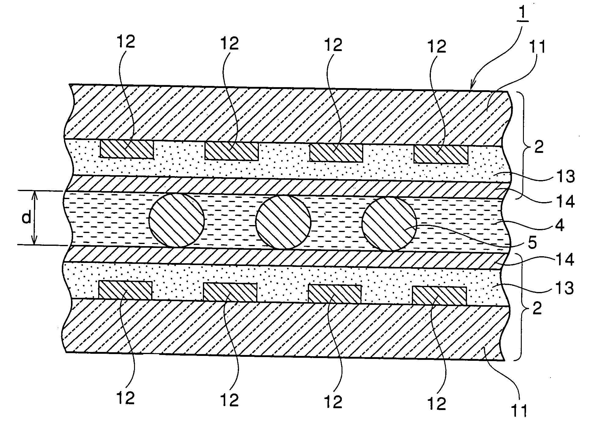
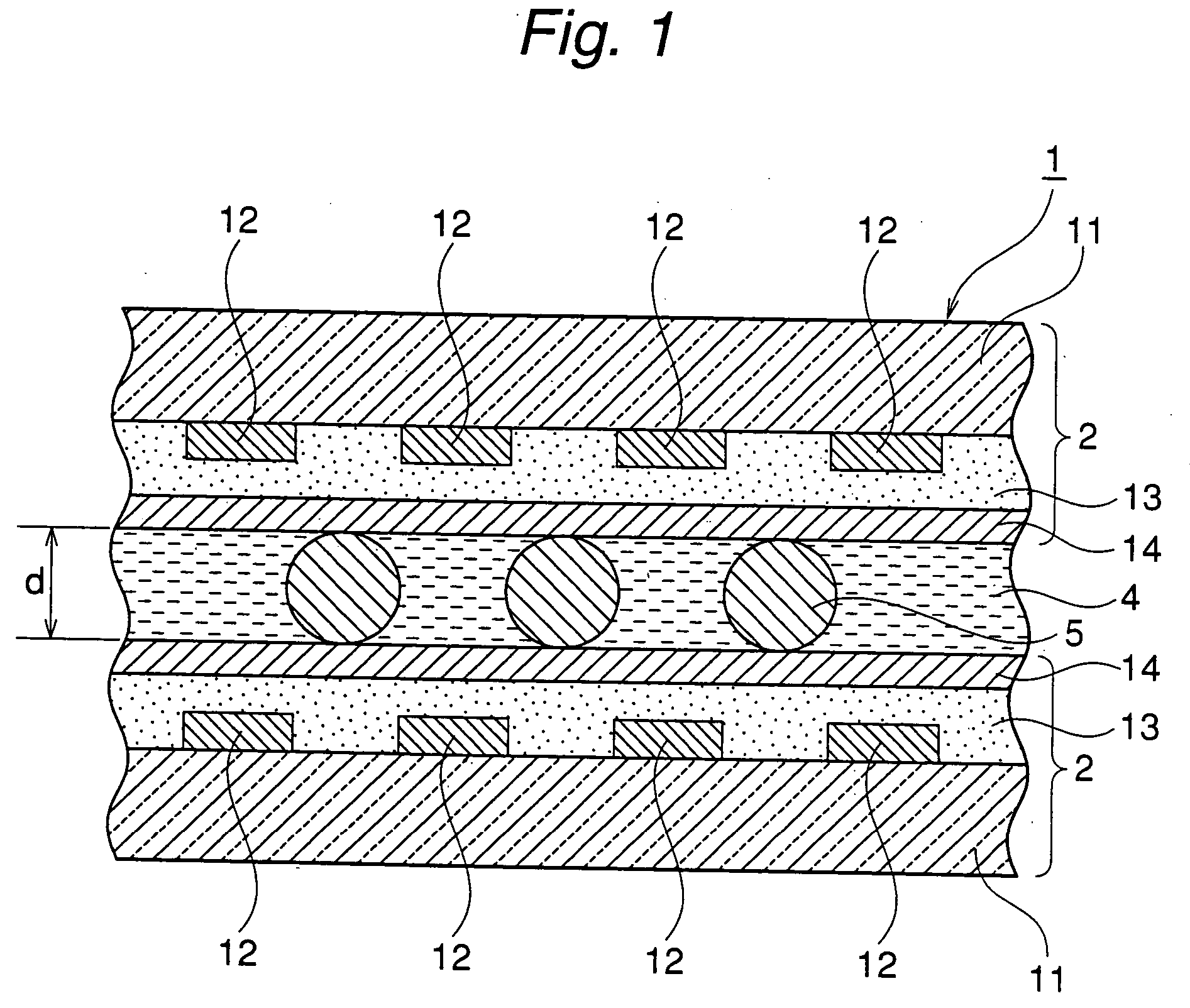
Liquid crystal display cell
- Summary
- Abstract
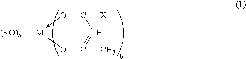
- Description
- Claims
- Application Information
AI Technical Summary
Benefits of technology
Problems solved by technology
Method used
Image

Examples
example 1
Preparation of Transparent Film-Forming Coating Solution
To 150 g of ethyl silicate 28 (SiO2 concentration: 28% by weight) as a matrix component precursor, 40 g of butyl cellosolve, 304.4 g of hexylene glycol, 0.4 g of nitric acid having a concentration of 61% by weight and 15 g of pure water were added, and they were stirred at room temperature for 2 hours. To the mixture, 15 g of an amphoteric ion-exchange resin (available from Mitsubishi Chemical Corporation, Diaion) was added, and they were stirred for 1 hour to perform deionization. Thereafter, the amphoteric ion-exchange resin was removed to obtain a dispersion of a partial hydrolyzate (oligomer) of ethyl silicate.
To the dispersion, 90 g of an inorganic ion-adsorbing fine particle sol having a solids concentration of 10% by weight obtained by homogeneously dispersing antimony pentoxide fine particles (Sb2O5.2.7H2O, ion adsorption capability: 2.4 mmol / g) having an average particle diameter of 20 nm as inorganic oxide fine pa...
example 2
A transparent film-forming coating solution (B) was prepared in the same manner as in Example 1, except that silica alumina fine particles (0.75SiO2.0.25Al2O3.0.3H2O) having an average particle diameter of 25 nm and ion adsorption capability of 0.5 mmol / g obtained by drying silica alumina (available from Catalysts & Chemicals Industries Co., Ltd., USB sol) were used as the inorganic oxide fine particles. Then, a transparent film and an alignment layer were formed in the same manner as in Example 1. Then, an average surface roughness and adhesion properties of the alignment layer were measured in the same manner as in Example 1.
The results are set forth in Table 2.
Further, a liquid crystal display cell (B) was prepared in the same manner as in Example 1. The resulting liquid crystal display cell (B) was evaluated on the mobil ion quantity, presence of structural defect and impact resistance.
The results are set forth in Table 2.
example 3
After the same transparent film as in Example 1 was formed, a ferroelectric liquid crystal (available from Clariant Japan, FELIX M4851 / 100, response time: 38 μs, tilt angle: 30.5° (room temperature)) having been blended with an acrylate monomer UCL-003 (available from Dainippon Ink & Chemicals Inc.) as a photo-functional resin monomer was enclosed to form a liquid crystal layer, and the liquid crystal layer was irradiated with ultraviolet rays (UV wavelength: 365 nm, irradiation intensity: 2 mW / cm2) for 240 seconds with application of a voltage to the liquid crystal cell, to prepare a liquid crystal display cell (C) having a liquid crystal layer thickness of 2 μm.
The resulting liquid crystal display cell (C) was evaluated on the mobil ion quantity, presence of structural defect and impact resistance.
The results are set forth in Table 2.
PUM
| Property | Measurement | Unit |
|---|---|---|
| Nanoscale particle size | aaaaa | aaaaa |
| Nanoscale particle size | aaaaa | aaaaa |
| Nanoscale particle size | aaaaa | aaaaa |
Abstract
Description
Claims
Application Information
 - Generate Ideas
- Intellectual Property
- Life Sciences
- Materials
- Tech Scout
- Unparalleled Data Quality
- Higher Quality Content
- 60% Fewer Hallucinations
Browse by: Latest US Patents, China's latest patents, Technical Efficacy Thesaurus, Application Domain, Technology Topic, Popular Technical Reports.
© 2025 PatSnap. All rights reserved.Legal|Privacy policy|Modern Slavery Act Transparency Statement|Sitemap|About US| Contact US: help@patsnap.com