Conditioning system and method for use in the measurement of mercury in gaseous emissions

Active Publication Date: 2005-03-24
TEKRAN INSTR CORPORTION
View PDF27 Cites 26 Cited by
  • Summary
  • Abstract
  • Description
  • Claims
  • Application Information

AI Technical Summary

Benefits of technology

[0011] In one broad aspect, the invention is generally directed to the use of silicon carbide as pyrolyzer material in a thermal pyrolysis unit. In another broad aspect, the invention is directed to the use of silicon nitride, silicon boride, or boron nitride as pyrolyzer material in a thermal pyrolysis unit. The inventors have realized that these materials provide the ability to reduce all forms of mercury to elemental form, and further, prevent recombination before the removal of acid gas species.

Problems solved by technology

However, these analyzers may suffer problems with sensitivity since the AA detectors generally have detection limits in the 1 μg/m3 range and cannot quantitate values of less than several μg/m3.
While these analyzers may be useful in monitoring the emissions of waste incinerators for example, they are less useful in monitoring mercury in power plant emissions where greater sensitivity is required.
This system, however, requires the complex preparation of two different, low mercury reagents on a continuing basis, and is subject to high maintenance when used for extended periods of time.
Use of liquid chemical agents may also produce toxic waste.
However, these analyzers typically suffer from recombination problems in the presence of hydrogen chloride (HCl) or chlorine (Cl2).
In particular, the very poor transport characteristics of mercury chloride (HgCl2) means that this component of sample gas will not reach the gold cartridge in a timely manner, resulting in erroneous readings and memory effects.
Even where direct AA analyzers are used, HgCl2 may not be detected at all within the M cell si

Method used


Image

  • Conditioning system and method for use in the measurement of mercury in gaseous emissions
  • Conditioning system and method for use in the measurement of mercury in gaseous emissions
  • Conditioning system and method for use in the measurement of mercury in gaseous emissions

Examples


Embodiment Construction

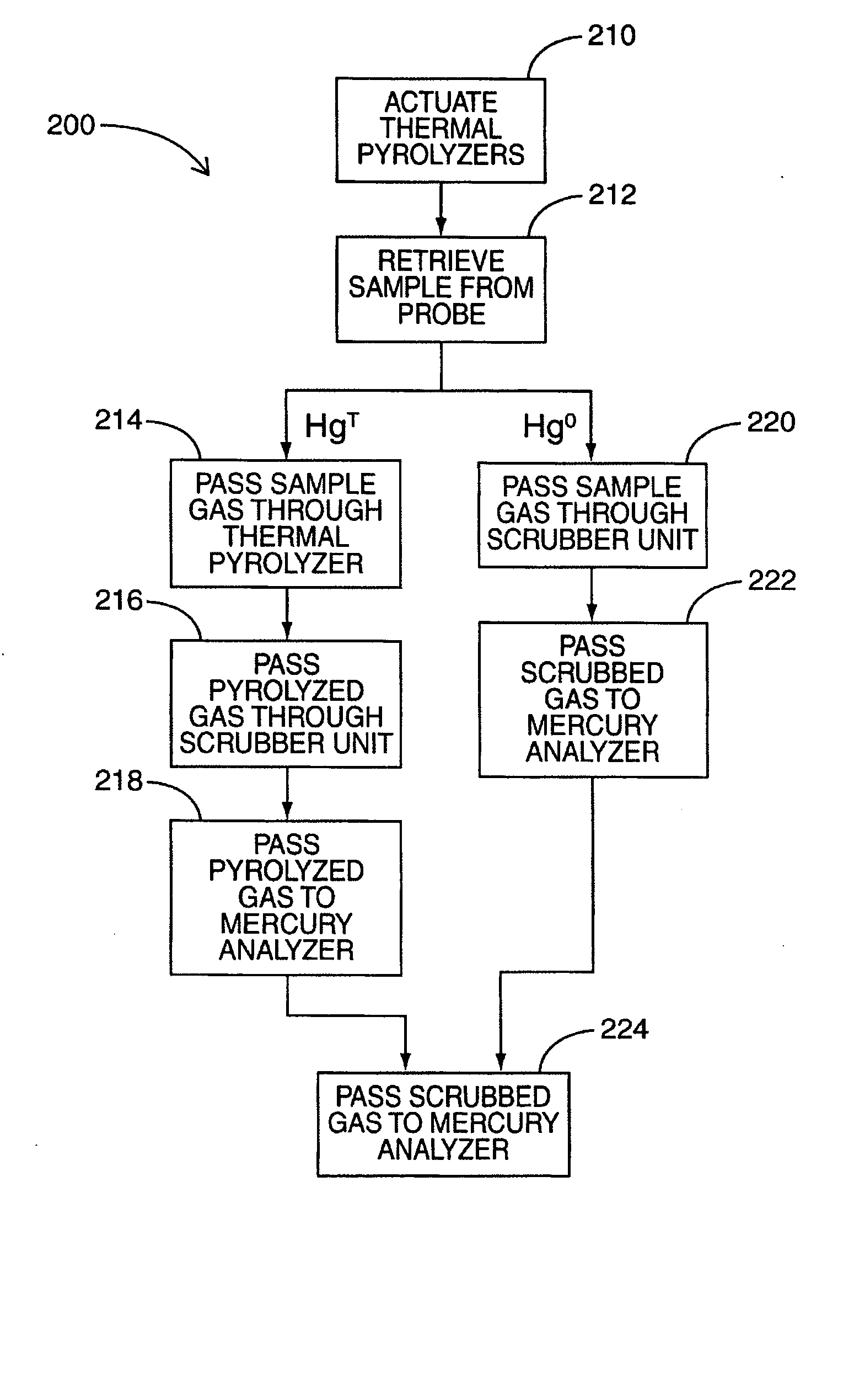
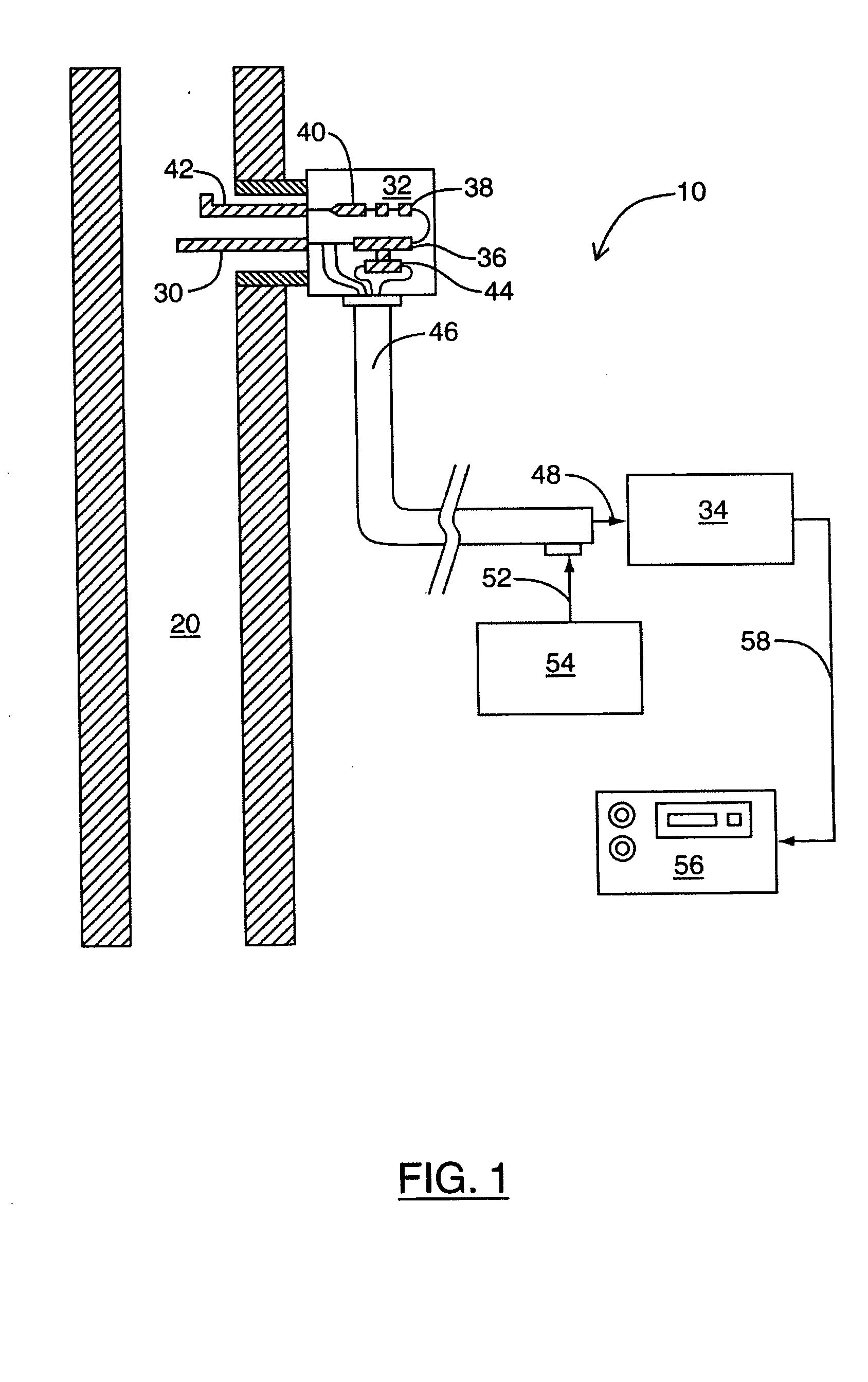
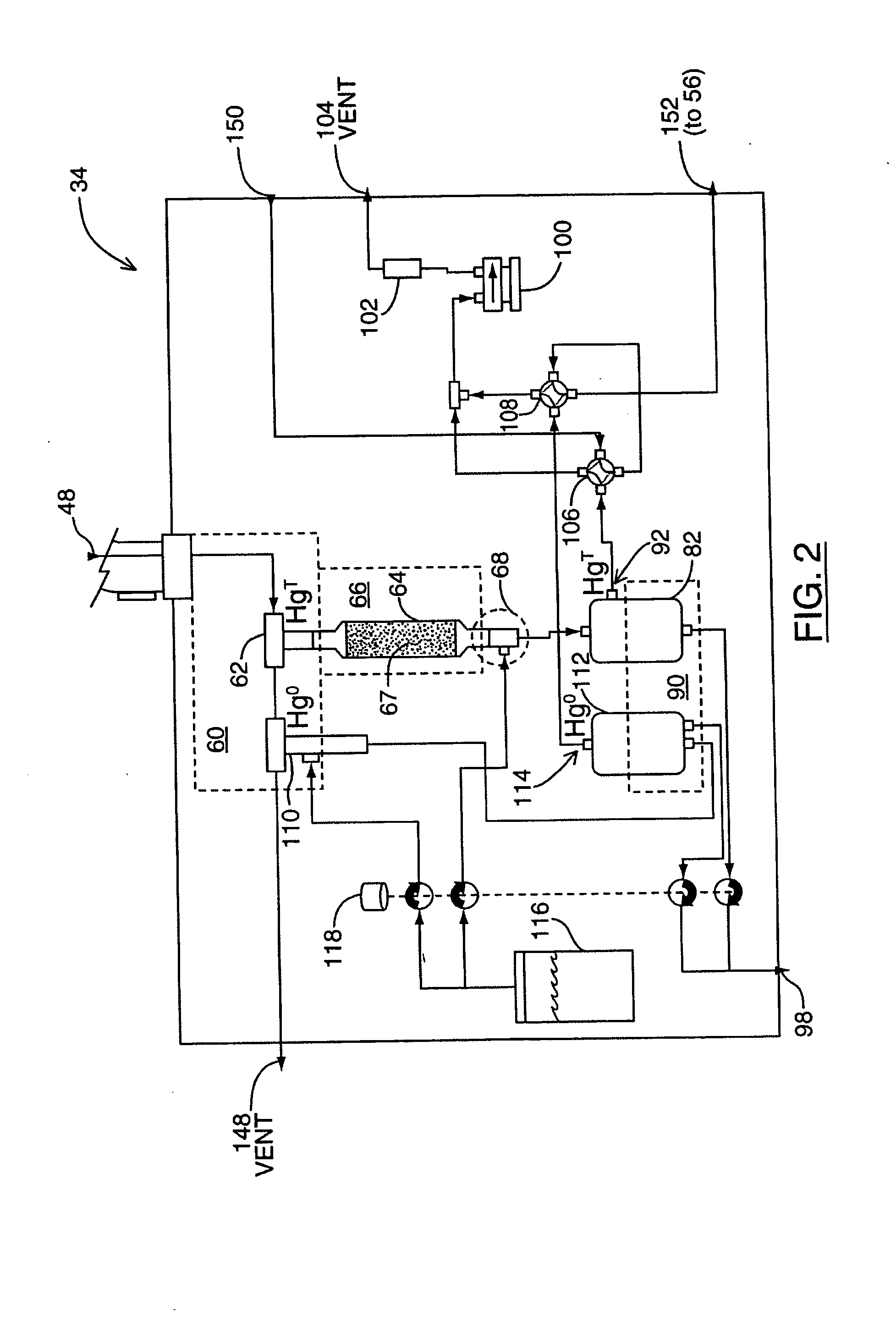
[0022] At least some embodiments of the invention relate generally to a system for monitoring mercury in gaseous emissions, comprising: a sampling probe for sampling the emissions; a conditioning module coupled to the sampling probe, which may be adapted to speciate mercury in the emissions, the conditioning module adapted for coupling to a mercury analyzer; a calibration module coupled to the sampling probe; and a controller coupled to the conditioning module and the calibration module. The conditioning module comprises a thermal converter and, in some embodiments, one or more scrubbing units. The thermal converter comprises one or more pyrolyzer units, wherein at least one of the pyrolyzer units comprises material composed of silicon carbide, silicon nitride, silicon boride, boron nitride, and / or other similar covalently bound material. At least one of the scrubbing units may comprise a coalescing filter used as an interference scrubber and gas / liquid separator. At least one of th...


PUM

PropertyMeasurementUnit
Hydrophobicityaaaaaaaaaa
Wetting tensionaaaaaaaaaa

Abstract

Embodiments of the invention relate generally to systems used to measure mercury in gaseous emissions. In one aspect, the invention is directed to the use of silicon carbide as material for a thermal pyrolysis unit. In another aspect, at least one of silicon nitride, silicon boride, and/or boron nitride is used as material for a thermal pyrolysis unit. In another aspect, the invention is directed to an improved pyrolyzer design, in which a thermal pyrolysis unit comprises a tailpiece that allows water to be injected at the heated exit of the thermal pyrolysis unit. In another aspect, the invention is directed to the use of a coalescing filter in a scrubbing unit. In another aspect, the invention is directed to the use of a hydrophobic filter element in a scrubbing unit. One or more of these elements may be used in a conditioning module of a continuous emissions monitoring system, for example.

Description

CROSS-REFERENCE TO RELATED APPLICATION [0001] This is a non-provisional application of U.S. application No. 60 / 503,894 filed Sep. 22, 2003. The contents of U.S. application No. 60 / 503,894 are incorporated herein by reference.FIELD OF THE INVENTION [0002] The present invention relates generally to mercury detection systems, and more particularly to conditioning systems and methods that may be employed in the measurement of gaseous mercury in combustion and process gas emissions. BACKGROUND OF THE INVENTION [0003] Governments, power utilities and researchers have recognized the need for a viable system to continuously detect and monitor mercury emissions in stack emissions and process gases. A number of proposed solutions exist in the prior art. [0004] For example, some known conventional direct wet chemical analyzers use wet chemical reagents to condition gas samples for subsequent analysis by atomic absorption (AA) detectors, for example. Stannous chloride, sodium borohydride, or ot...

Claims


Application Information

Patent Timeline
IPC IPC(8): C22B7/00C22B43/00
CPCC22B7/001C22B43/00G01N1/2202G01N33/0013G01N1/4022G01N33/0011G01N1/2258Y02P10/20B01D53/64B01D53/346B01D53/30B01D2257/602
Inventor SCHAEDLICH, FRANK H.SCHNEEBERGER, DANIEL R.
Owner TEKRAN INSTR CORPORTION
Why Eureka
Try Eureka