Thermal barrier composition, a superalloy machine part provided with a coating having such a composition, a ceramic coating, and a method of fabricating the coating

a technology of composition and composition, which is applied in the direction of solid-state diffusion coating, liquid fuel engine components, non-positive-discharge fluid engine, etc., can solve the problem of significant delamination between the coating and the substrate, and achieve the effect of reducing the thermal conductivity of zirconia

Active Publication Date: 2005-03-24
SN DETUDE & DE CONSTR DE MOTEURS DAVIATION S N E C M A
View PDF4 Cites 17 Cited by
  • Summary
  • Abstract
  • Description
  • Claims
  • Application Information

AI Technical Summary

Benefits of technology

[0014] An object of the present invention is to provide a novel thermal barrier composition based on zirconia that makes it possible to obtain a thermal barrier coating having lower thermal conductivity than that of the yttrium-containing zirconia usually used for thermal barriers (or lower than that of the composition of FR 2 798 864), while increasing the high-temperature strength and thermal stability properties of said yttrium-containing zirconia (or of the composition of FR 2 798 864).
[0015] An object of the present invention is thus to provide a novel zirconia-based thermal barrier composition making it possible to obtain a thermal barrier composition having low thermal conductivity without affecting high-temperature strength for operating temperatures lying in the range 1100° C. to 1500° C.
[0016] The idea on which the present invention is based is to consider that there is a relationship between a reduction in the qualities, in particular in terms of high-temperature strength, of the coating obtained from the thermal barrier and an increase in the number of oxygen vacancies in the crystal lattice of the ceramic.

Problems solved by technology

Usually, it is found that thermal barriers which give rise to a significant discontinuity in thermal conductivity run the risk of significant delamination between the coating and the substrate, or more precisely at the interface between the underlayer and the ceramic thermal barrier.

Method used


Image

  • Thermal barrier composition, a superalloy machine part provided with a coating having such a composition, a ceramic coating, and a method of fabricating the coating
  • Thermal barrier composition, a superalloy machine part provided with a coating having such a composition, a ceramic coating, and a method of fabricating the coating

Examples


Embodiment Construction

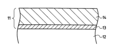
[0044] The machine part shown in FIG. 1 comprises a thermal barrier coating 11 deposited on a substrate 12 of superalloy, such as superalloy based on nickel and / or cobalt. The thermal barrier coating 11 comprises a metal underlayer 13 deposited on the substrate 12, and a ceramic layer 14 of composition in accordance with the invention, deposited on the underlayer 13.

[0045] The underlayer 13 may be an alumina-forming alloy that withstand oxygen corrosion, such as an alloy suitable for forming a protective layer of alumina by oxidation, an alloy of the MCrAlY type (M being a metal selected from nickel, cobalt, iron, or a mixture of said metals), or a nickel or cobalt aluminide optionally modified by adding a metal selected from platinum, chromium, palladium, ruthenium, iridium, osmium, rhodium, or a mixture of these metals and / or a reactive element selected from zirconium (Zr), hafnium (Hf), and yttrium (Y).

[0046] The ceramic layer 14 is constituted by a zirconia base, a trivalent o...


PUM

PropertyMeasurementUnit
Fractionaaaaaaaaaa
Fractionaaaaaaaaaa
Fractionaaaaaaaaaa

Abstract

The invention relates to a ceramic thermal barrier composition of low conductivity and high high-temperature strength. In characteristic manner, the composition comprises a zirconia base, at least one trivalent oxide enabling the zirconia to be stabilized and enabling the thermal conductivity of the zirconia to be reduced in optimum manner, and at least one pentavalent oxide enabling the content of oxygen vacancies to be reduced so as to make it substantially equal to that of a partially stabilized zirconia. Preferably, said trivalent oxide is present with a molar content constituted by a first portion enabling the zirconia to be stabilized partially and a second portion which introduces point defects into the lattice said pentavalent oxide is present with a molar concentration equal to said molar concentration of said second portion of the trivalent oxide. The invention is applicable to making a superalloy machine part having a ceramic coating with said composition, and possibly also a bonding underlayer.

Description

[0001] The invention relates to a thermal barrier composition having low thermal conductivity, to a machine part made of superalloy and protected by a ceramic coating having such a composition, to said ceramic coating, and to a method of fabricating the ceramic coating. BACKGROUND OF THE INVENTION [0002] Efforts to increase the efficiency of turbomachines, in particular in the field of aviation, and to reduce fuel consumption and emissions of polluting gases and unburned fuel have led to a move towards stoichiometric mixtures for fuel combustion. This situation is accompanied by an increase in the temperature of the gas leaving the combustion chamber and going towards the turbine. [0003] Consequently, it has been necessary to adapt the materials of the turbine to such an increase in temperature, by improving techniques for cooling turbine blades (hollow blades) and / or by improving the properties of such materials to enable them to withstand high temperatures. [0004] This second tech...

Claims


Application Information

Patent Timeline
IPC IPC(8): C04B35/486C23C4/02C23C4/10C23C4/11C23C8/10C23C28/00C23C30/00F01D5/28F02C7/00
CPCC04B35/486C23C4/02C23C28/321C23C28/3215C23C28/3455C23C30/00Y10T428/12618Y02T50/67Y02T50/671F05D2230/90F05D2300/611F05D2300/2118F01D5/288Y02T50/60
InventorLECLERCQ, BERANGEREMEVREL, REMYAZZOPARDI, ALBANMALIE, ANDRESAINT-RAMOND, BERTRAND
OwnerSN DETUDE & DE CONSTR DE MOTEURS DAVIATION S N E C M A