
Planographic printing plate precursor

a technology of planographic printing plate and precursor, which is applied in the direction of auxillary/base layers of photosensitive materials, instruments, photosensitive materials, etc., can solve the problems of low degree of sensitivity, insufficient highlight reproducibility, and diminished difference between an image region and a non-image region, so as to improve the reproducibility of highlights and reduce the number of images. , the effect of excellent film strength and excellent dissolution

Inactive Publication Date: 2005-03-24
FUJIFILM CORP +1
View PDF23 Cites 29 Cited by
  • Summary
  • Abstract
  • Description
  • Claims
  • Application Information

AI Technical Summary

Benefits of technology

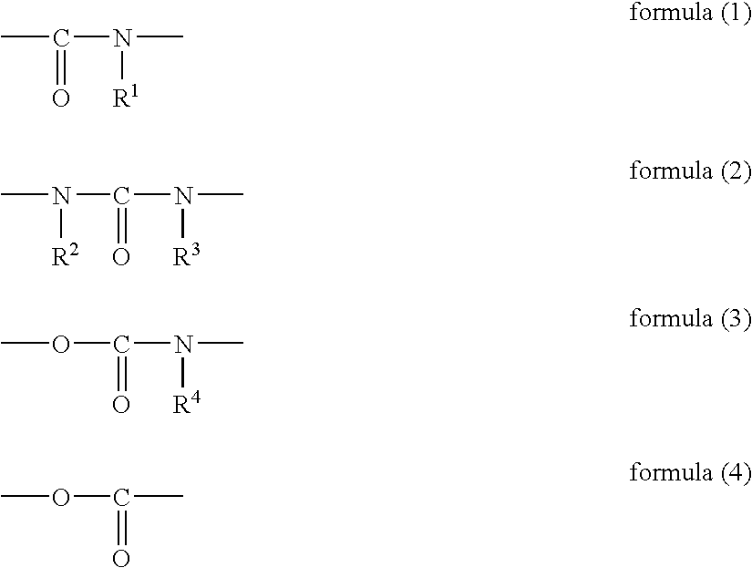
In the specific alkali-soluble resin, the specific bond is essential for enhancing printing durability and chemical resistance as the effects of the invention. The specific bond in the invention is represented by the following formulae (1) to (4):

Problems solved by technology

Thus in the vicinity of the support, the quantity of heat used in image formation, i.e., for solubilization of the recording layer, is reduced due to diffusion of heat into the support, which results in a lower degree of sensitivity.
Accordingly, a problem arises insofar that elimination of the capacity of inhibiting development of the recording layer is inadequate in a non-image region, and thus the difference between an image region and a non-image region diminished, and highlight reproducibility becomes inadequate.
However, such a recording layer is chemically inferior even in an image region, and has a disadvantage insofar that it is inferior in terms of chemical resistance, and can be easily damaged by an ink washing solvent used in a developer or during printing, or by a plate cleaner etc.
This planographic printing plate precursor exhibits an improvement in sensitivity, but is inadequate in terms of chemical resistance.
In this case, other problems arises such as unsatisfactory adhesion of the support to the recording layer and inferior printing durability.
The former material of JP-A No. 11-218914 is excellent in terms of sensitivity and chemical resistance, but entails a problem insofar that the strength of resin used in the lower layer is inadequate, and there is still room for improvement in terms of printing durability.
The latter method of JP-A No. 11-194483 also involves problems insofar that the alkali-soluble resin used is inferior in terms of chemical resistance, and thus a recording layer may be eluted with a solvent component contained in a plate cleaner, or the solvent component may penetrate to the interface between the substrate and the lower layer and reduce the adhesiveness of the recording layer to the substrate, thereby causing the recording layer to peel off easily.
In short, in the aforementioned two references, printing durability, which is dependent on the film strength of the lower layer and chemical resistance can hardly be made compatible with each other.

Method used


Image

  • Planographic printing plate precursor
  • Planographic printing plate precursor
  • Planographic printing plate precursor

Examples


examples

Hereinafter, the present invention is described by reference to the Examples, but the invention is not limited to the Examples.

examples 1 to 6

[Preparation of a Support]

<Aluminum Plate>

An aluminum alloy containing 0.06% by mass Si, 0.30% by mass Fe, 0.025% by mass Cu, 0.001% by mass Mn, 0.001% by mass Mg, 0.001% by mass Zn and 0.03% by mass Ti, the balance being Al and inevitable impurities, was used to prepare a melt. The melt was then subjected to cleaning treatment, filtered and then formed by means of a DC casting method into an ingot of 500 mm in thickness and 1200 mm in width. After a surface layer of 10 mm in average thickness was shaved with a surface shaving machine, the ingot was kept at 550° C. for about 5 hours, and when the temperature was reduced to 400° C., the ingot was formed with a hot rolling mill into a rolled plate of 2.7 mm in thickness. Then, the plate was subjected to heat treatment at 500° C. with a continuous annealing device, finished with cold rolling to produce a plate of 0.24 mm in thickness, and an aluminum plate of JIS 1050 material was thus obtained.

The minor axis of the average cr...

examples 7 to 10

[Preparation of a Support]

The surface of an aluminum plate (material: JIS A1050) of 0.30 mm in thickness was subjected to etching treatment with caustic soda in a concentration of 30 g / l and aluminum ions in a concentration of 10 g / l at a solution temperature of 60° C. for 10 seconds, then washed with running water, neutralized with 10 g / l nitric acid and washed with water. The support was subjected to electrochemical surface roughening treatment with a sine-wave electric current of 500 C / dm2 in an alternating waveform at an applied voltage (Va) of 20 V in an aqueous solution containing hydrogen chloride in a concentration of 15 g / l and aluminum ions in a concentration of 10 g / l at a solution temperature of 30° C. After washing with water, the support was subjected to etching treatment with caustic soda in a concentration of 30 g / l and aluminum ions in a concentration of 10 g / l at a solution temperature of 40° C. for 10 seconds and then washed with running water.

Then, the suppor...


PUM

PropertyMeasurementUnit
concentrationaaaaaaaaaa
alkali-solubleaaaaaaaaaa
acidaaaaaaaaaa

Abstract

The planographic printing plate precursor of the invention includes a recording layer capable of forming an image upon irradiation with infrared rays, wherein the recording layer comprises (A) an alkali-soluble resin having, in a main chain, a structural unit containing at least one type of bond selected from an amide bond, urea bond, urethane bond and ester bond and having at least one type of acid group selected from a phenolic hydroxyl group, sulfonamide group and active imide group, and (B) an infrared absorbing agent. The invention provides a positive-working planographic printing plate precursor excellent in printing durability and chemical resistance.

Description

CROSS-REFERENCE TO RELATED APPLICATION This application claims priority under 35 USC 119 from Japanese patent document, No. 2003-321022, the disclosure of which is incorporated by reference herein. BACKGROUND OF THE INVENTION 1. Field of the Invention The present invention relates to a planographic printing plate precursor, and in particular to a positive-type planographic printing plate precursor capable of direct plate-making from digital signals in computers etc. 2. Description of the Related Art Development of lasers has been remarkable in recent years. In particular, solid lasers and semiconductor lasers which have a high power output but are small in size, and with an emission range in the near infrared to infrared range, have become readily available. In the field of planographic printing, these lasers are extremely useful as sources of light at a time of direct plate-making from digital data in computers etc. The positive-type planographic printing plate precursor for ...

Claims


Application Information

Patent Timeline
Patent Type & Authority Applications(United States)
IPC IPC(8): G03F7/004B41C1/10G03F7/00
CPCB41C1/1008B41C2210/266B41C2201/04B41C2201/06B41C2201/10B41C2201/12B41C2201/14B41C2210/02B41C2210/06B41C2210/14B41C2210/22B41C2210/24B41C2210/26B41C2210/262B41C2210/264B41C1/1016
Inventor NAKAMURA, IPPEIMAEMOTO, KAZUO
Owner FUJIFILM CORP
Learn More