
Metal material coated with metal oxide and/or metal hydroxide coating film and method for production thereof

a metal oxide and metal hydroxide technology, applied in the direction of electrolytic inorganic material coating, solid-state diffusion coating, coating, etc., can solve the problems of substrate deterioration, violent metal elution reaction, substrate corrosion, etc., to facilitate the control of potential, increase the deposition rate, and facilitate the effect of controlling potential

Inactive Publication Date: 2005-03-31
NIPPON STEEL CORP
View PDF15 Cites 12 Cited by
  • Summary
  • Abstract
  • Description
  • Claims
  • Application Information

AI Technical Summary

Benefits of technology

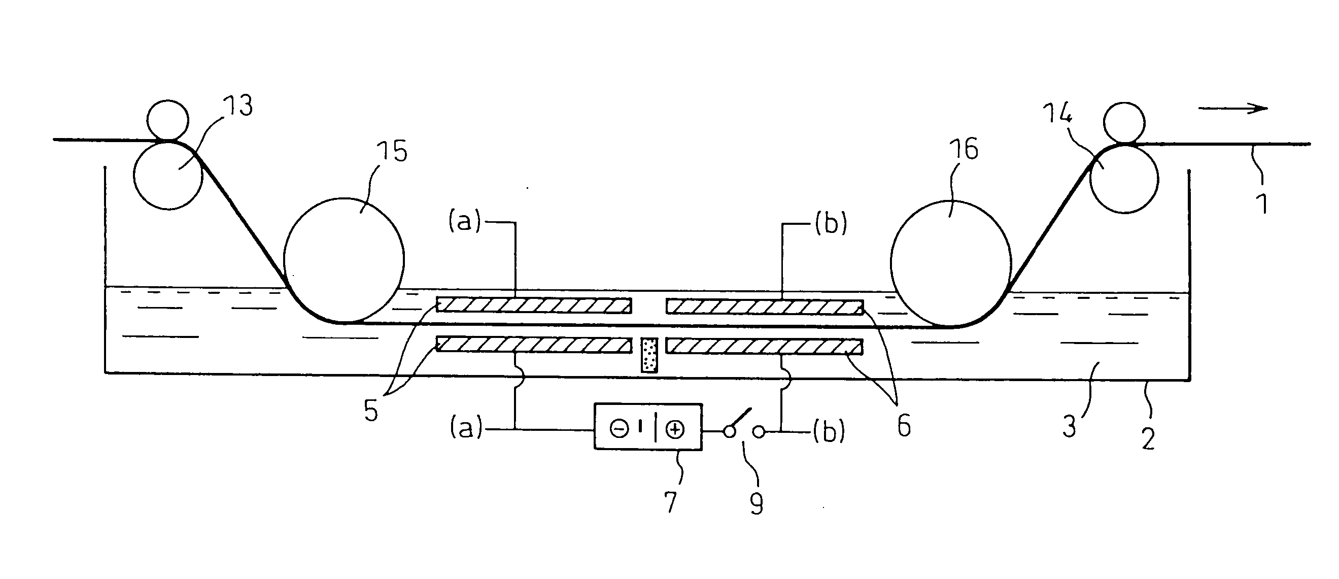
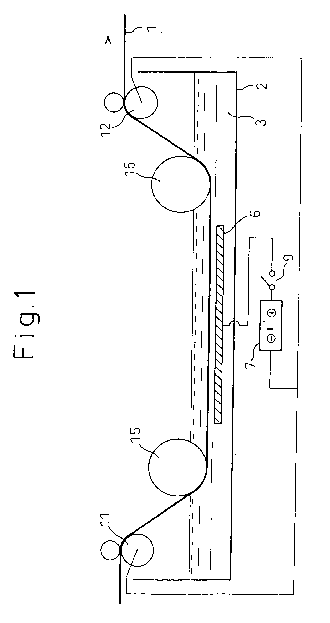
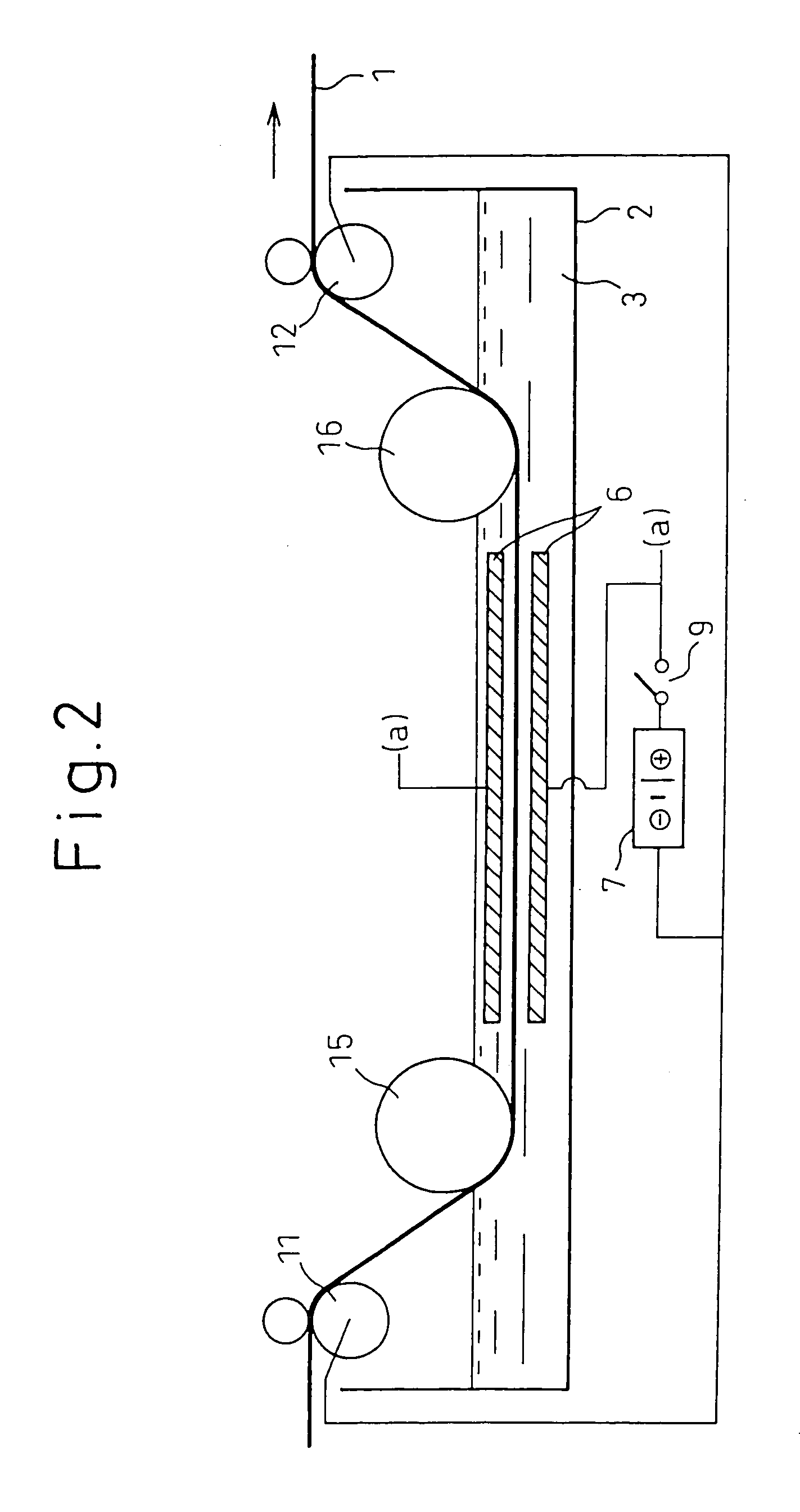
Thus when considering the film formability, it is clearly a requirement to control the hydrogen generating and metal ion elution and deposition reactions, or in other words, to control the pH of the solution bath to within a suitable range. Moreover, by shorting the substrate and the metal material having a lower standard electrode potential, the hydrogen generating reaction will occur at the substrate and the metal elution reaction will occur at the metal material with a lower standard electrode potential, thereby suppressing corrosion of the substrate metal material. In this case as well, however, film formation is still inhibited by the hydrogen reduction reaction at the substrate, and therefore the pH of the solution bath must obviously be set to within a suitable range. In addition, it was found that when the low standard electrode potential material is shorted before immersing the substrate, a higher film forming rate is achieved than by simply immersing the substrate. This is believed to be because in the latter case, metal elution reaction shifts to deposition reaction thereby causing the eluted ion concentration to be reduced by film formation, whereas with shorting, the metal elution reaction and deposition reaction occur in independent reaction zones such that elution of the metal ion proceeds constantly.
If the anodic reaction and cathodic reaction of the insoluble material and the substrate to be deposited are controlled, then hydrogen ion reduction reaction will occur on the substrate and progress of the reactions and increasing pH at the interface will result in deposition of the metal oxide and / or metal hydroxide. It was surmised that the deposition rate may be increased if the hydrogen generating reaction and interface pH increase can be controlled in a range that does not inhibit film formation. Boron ion or aluminum ion may also be added to the treatment solution to form stabler fluorides against fluorine ion consumption. It was thus confirmed that a uniform coating can be formed in a short time by controlling the potential to a level which does not inhibit the deposition reaction by hydrogen gas generation. If the treatment solution pH is too low, the hydrogen reduction reaction tends to occur violently, and it therefore became clear that setting the pH of the solution bath to within a suitable range can facilitate control of the potential. That is, control of the hydrogen generating reaction allowed the deposition rate to be dramatically increased.

Problems solved by technology

Either or both the metal elution reaction and hydrogen reduction reaction are necessary for the film forming reaction to proceed, but excessive metal elution reaction can cause deterioration of the substrate, while excessive hydrogen generation can also prevent complete film formation or inhibit the deposition reaction.
For example, if the treatment solution pH is too low, immersion of the substrate can result in violent metal elution reaction and hydrogen reduction reaction, such that no deposit forms and the substrate becomes corroded.

Method used


Image

  • Metal material coated with metal oxide and/or metal hydroxide coating film and method for production thereof
  • Metal material coated with metal oxide and/or metal hydroxide coating film and method for production thereof
  • Metal material coated with metal oxide and/or metal hydroxide coating film and method for production thereof

Examples


example 1

This example illustrates the first aspect of the invention.

Different treatment solutions were used to form films in the manner described below, and the deposition states were evaluated. The substrates, treatment solutions, treatment conditions and results are shown in Tables 1 and 2.

The deposition state was evaluated by visual observation of the condition after film formation and after 90° bending, with ◯ indicating absence of peeling, and x indicating presence of peeling. The surface condition was evaluated by scanning electron microscope observation at 5000× magnification, and evaluation was made based on 4 arbitrarily selected locations, with x indicating cracks at 2 or more locations, ◯ indicating a crack at 1 location, and ⊚ indicating no cracks. When necessary, the cross-section was observed to examine the coating structure.

The substrate for film formation was designated as metal material A, and the metal with a lower standard electrode potential than metal material A w...

example 2

This example illustrates the second aspect of the invention.

Different treatment solutions were used to form films in the manner described below, and the deposition states were evaluated. The substrates, treatment solutions, treatment conditions and results are shown in Tables 3 and 4.

The deposition state was evaluated by visual observation of the condition after film formation and after 90° bending, with ◯ indicating absence of peeling, and x indicating presence of peeling. The surface condition was evaluated by scanning electron microscope observation at 5000× magnification, and evaluation was made based on 4 arbitrarily selected locations, with x indicating cracks at 2 or more locations, ◯ indicating a crack at 1 location, and ⊚ indicating no cracks. The mass was measured before and after deposition, and the difference was divided by the deposition area to calculate the amount of deposition per unit area. When necessary, the cross-section was observed to examine the coating s...

example 3

[Experiment Nos. 201-228]

Films were formed by immersion of various plated steel sheets as the base materials in aqueous solutions of ammonium hexafluorosilicate, ammonium hexafluorotitanate and ammonium hexafluorozirconate. The film formation was carried out for 5 minutes at room temperature, and the film formation was followed by water rinsing and air drying (see Table 5).

[Experiment Nos. 301-321]

Films were formed on various plated steel sheets as the base materials in aqueous solutions of ammonium hexafluorosilicate, ammonium hexafluorotitanate and ammonium hexafluorozirconate, by cathode electrolysis using platinum as the counter electrode. The film formation was carried out for 5 minutes at room temperature, and the film formation was followed by water rinsing and air drying (see Table 6).

[Experiment Nos. 401-421]

Films were formed on various plated steel sheets as the base materials in aqueous solutions of ammonium hexafluorosilicate, ammonium hexafluorotitanate and ammo...


PUM

PropertyMeasurementUnit
molar ratioaaaaaaaaaa
thicknessaaaaaaaaaa

Abstract

It is an object of the invention to provide a method for production of various oxide and / or hydroxide coatings with various functions and constructions on metal materials from aqueous solutions, and metal materials having such coatings. There are provided specifically a method for production of a metal oxide and / or metal hydroxide coated metal material characterized by immersing a metal material or electrolyzing a conductive material in an aqueous treatment solution at pH 2-7 containing metal ion and fluorine ion in a 4-fold molar ratio with respect to the metal ion, and / or containing a complex ion comprising at least a metal and fluorine in a 4-fold molar ratio with respect to the metal, to form on the surface of the metal material a metal oxide and / or metal hydroxide coating containing the metal ion, as well as a metal oxide and / or metal hydroxide coated metal material characterized by having a metal oxide and / or metal hydroxide coating produced by the method.

Description

TECHNICAL FIELD The present invention relates to metal oxide and / or metal hydroxide coated metal materials and to a method for their production. BACKGROUND ART Vapor phase methods such as sputtering or CVD and liquid phase methods such as sol-gel methods have been used as methods for producing various types of oxide films, but they have been limited in the following ways. Vapor phase methods accomplish film formation on substrates in the vapor phase and therefore require costly equipment in order to achieve a vacuum system. Means are also necessary for heating the substrate prior to film formation. It is also difficult to form films on substrates with irregularities or curved surfaces. Sol-gel methods, as liquid phase methods, require firing after application and therefore result in generation of cracks and dispersion of metal from the substrate. Because of the volatile portion, it is difficult to form a dense coating. One liquid phase method wherein an aqueous fluorine compoun...

Claims


Application Information

Patent Timeline
Patent Type & Authority Applications(United States)
IPC IPC(8): C23C22/34C23C22/68C25D9/04
CPCC23C22/34C25D9/04C23C22/68C23C22/06
Inventor SHOJI, HIROMASASUGIURA, TSUTOMU
Owner NIPPON STEEL CORP
Learn More