
Optical sheet and backlight unit using the same

a backlight unit and optical sheet technology, applied in the field of optical sheets, can solve the problems of heat-induced bending of the backlight unit, and achieve the effect of reducing the risk of bending

Inactive Publication Date: 2005-03-31
KEIWA INCORPORATED
View PDF3 Cites 26 Cited by
  • Summary
  • Abstract
  • Description
  • Claims
  • Application Information

AI Technical Summary

Benefits of technology

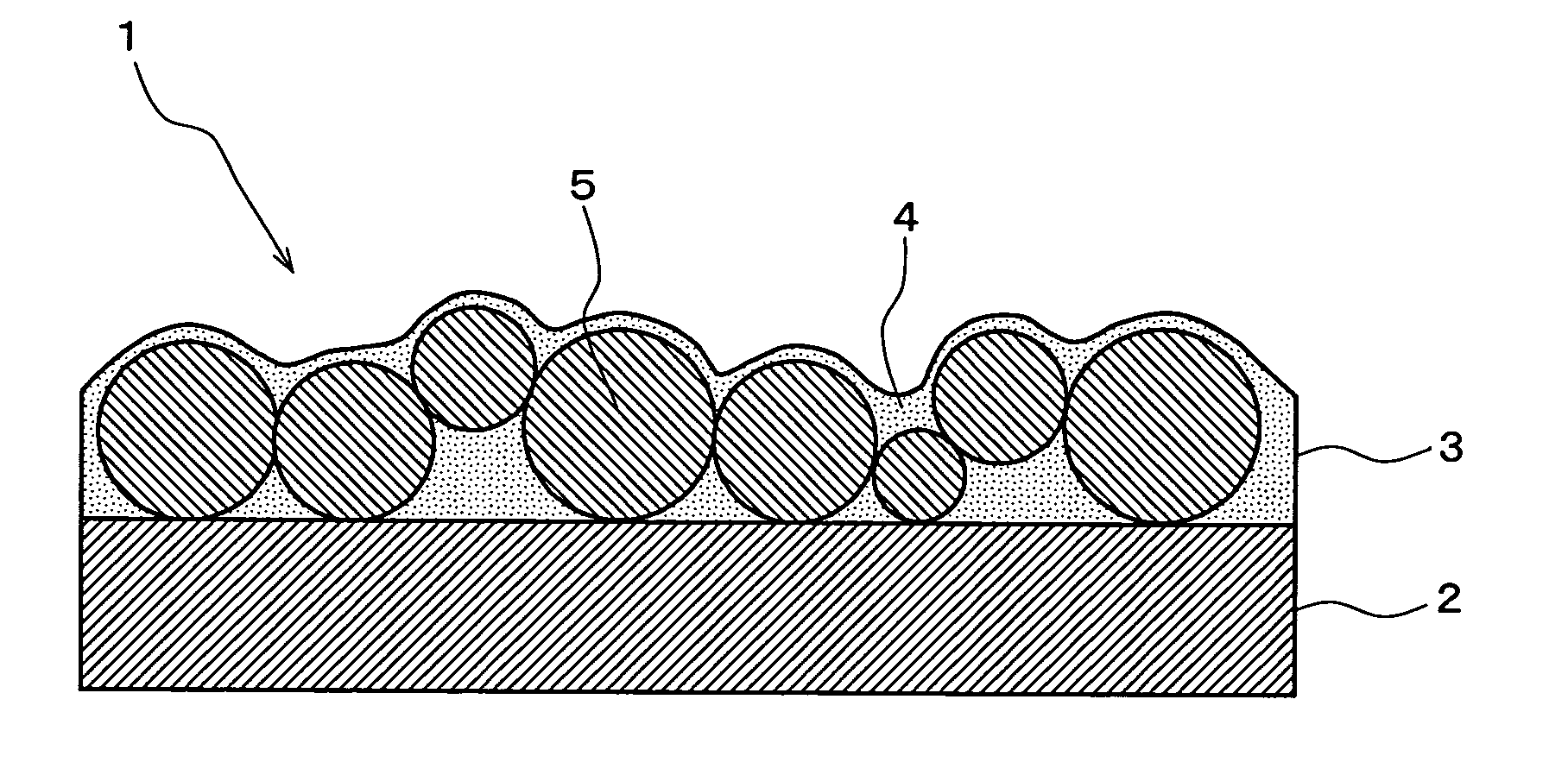
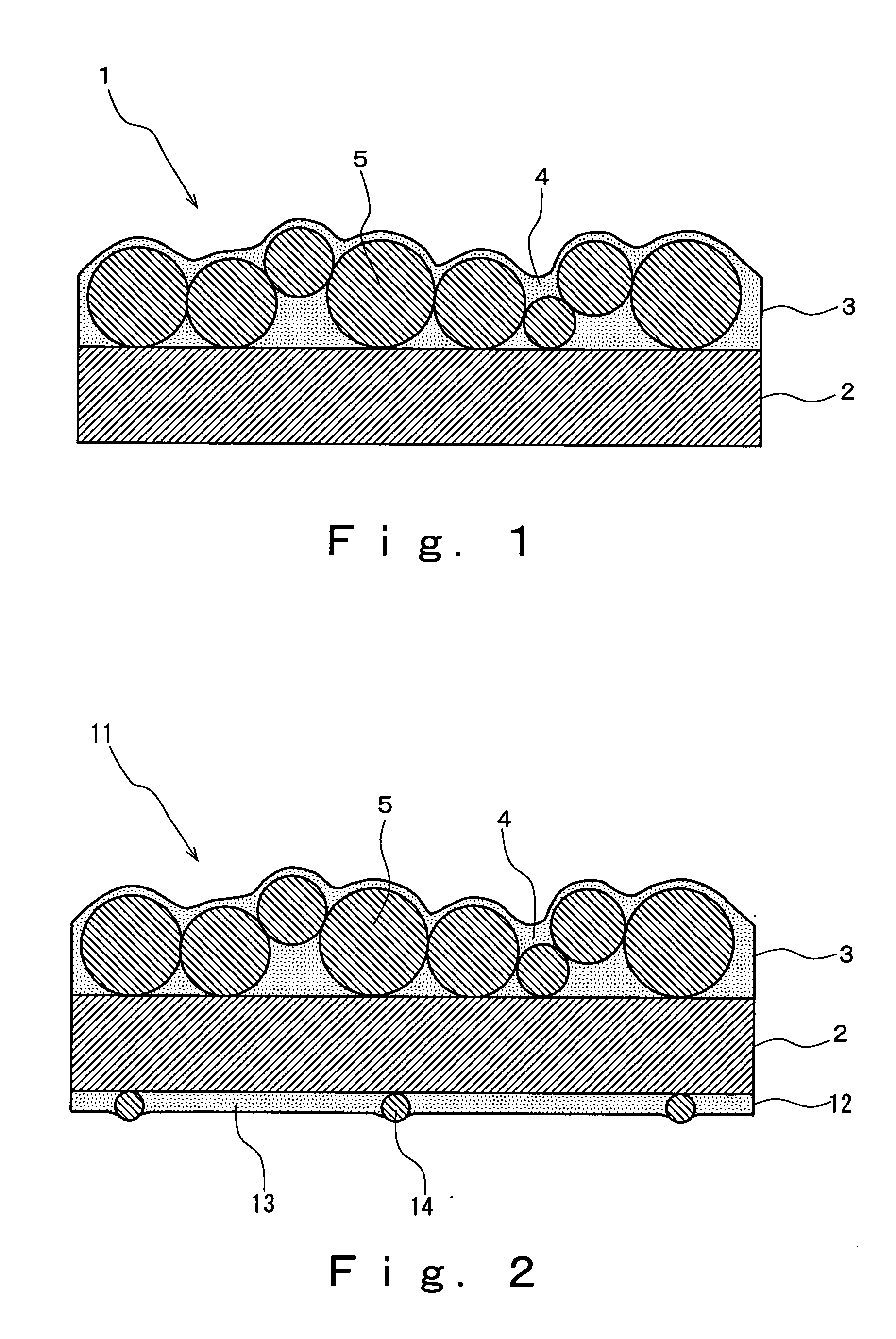
The present invention provides an optical sheet with excellent heat resistance, moisture resistance, thermal dimensional stability, weather resistance, and light diffusion function. The optical sheet is made by coating a transparent substrate with an optical layer made of a copolymer and a fine inorganic filler. The copolymer includes a cycloalkyl group, an iso-butyl group, or a tert-butyl group, which improves moisture resistance and hardness of the optical layer. The optical sheet has improved heat resistance and moisture resistance, and can suppress bending and yellowing caused by heat and ultraviolet rays. The use of the optical sheet in a backlight unit reduces the occurrence of brightness unevenness and lowering of brightness.

Problems solved by technology

More specifically, as the moisture resistance of the light diffusion sheet is reduced, heat-induced bending in the backlight unit is liable to occur.

Method used


Image

  • Optical sheet and backlight unit using the same
  • Optical sheet and backlight unit using the same
  • Optical sheet and backlight unit using the same

Examples


example 1

A dispersion of composite fine particle A including a fine inorganic filler in n-butyl acetate, and a solution of the copolymer (1) were prepared, and mixed to give an inorganic matter content in the solid content (fine inorganic filler content) of 40% by weight. Accordingly, a polymer composition containing the copolymer (1) and the composite fine particles was obtained. To this polymer composition were blended 100 parts (amount calculated on the basis of the solid content per 100 parts of the copolymer) of acrylic resin beads (“MBX-5” manufactured by Sekisui Plastics Co., Ltd.) having a mean particle size of 5 μm as a light diffusing agent, and thereto was further blended polyfunctional isocyanate (“Coronate HX” manufactured by NIPPON POLYURETHANE INDUSTRY CO., LTD.) after weighing to give an amount yielding OH group / NCO group of 1 (equivalent ratio). Thus resulting coating liquid for an optical layer was applied on a polyethylene terephthalate film (substrate layer) having a thi...

examples 2 to 7

Optical sheets of Examples 2 to 7 were produced using copolymers (2) to (7) shown in Table 1 as a copolymer. Fundamental procedures for producing these optical sheets conformed to the aforementioned Example 1 (The same is applied to in the followings). Conditions for producing these optical sheets and results of evaluation are shown in Table 2.

examples 8 to 9

Optical sheets of Examples 8 and 9 were produced using colloidal silica (“SNOWTEX®” manufactured by Nissan Chemical Industries, Ltd.) B having a mean particle size of 15 nm as a fine inorganic filler. Conditions for producing these optical sheets and results of evaluation are shown in Table 2.


PUM

PropertyMeasurementUnit
particle sizeaaaaaaaaaa

Abstract

An object of the present invention is to provide optical sheets having excellent heat resistance, moisture resistance, thermal dimensional stability and weather resistance, which hardly give rise to bending, yellowing and the like even though they receive generated heat from a lamp and ultraviolet ray irradiation, and to provide backlight units in which reduction of the occurrence of lack in uniformity of the brightness and lowering of the brightness is achieved using the optical sheet. The optical sheet of the present invention has a transparent substrate layer, and an optical layer overlaid to the front face side of the substrate layer. This optical layer includes a light diffusing agent in the binder. This binder is formed from a polymer composition containing (A) a copolymer and (B) a fine inorganic filler. This copolymer (A) includes at least one of a recurring unit derived from a (meth)acrylic ester having a cycloalkyl group, a recurring unit derived from an iso-butyl (meth)acrylate or a recurring unit derived from a tert-butyl (meth)acrylate.

Description

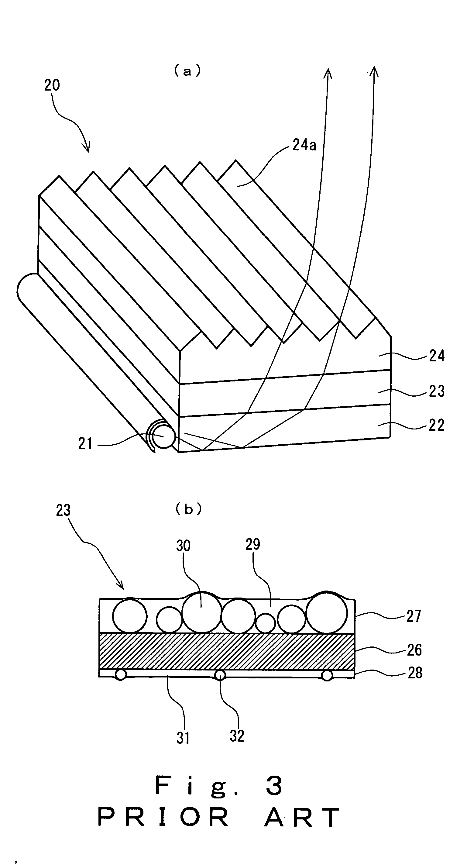
BACKGROUND OF THE INVENTION 1. Field of the Invention The present invention relates to optical sheets predominantly having a function to diffuse transmitted rays of light (light diffusion function), which are suitable for a backlight of a liquid crystal display device, in particular, and backlight units in which this optical sheet is used. 2. Description of the Related Art Liquid crystal display devices in widespread use have been in a backlight system where light emission is executed by irradiating onto a liquid crystal layer from the back face. In such a type of a display device, a backlight unit which is an edge light type, an immediate beneath type or the like is provided to an under face side of the liquid crystal layer. Such a backlight unit 20 of an edge light type is generally equipped with a rod-shaped lamp 21 for use as a light source, an optical waveguide plate 22 having a square plate shape disposed so that the edge thereof abuts along the lamp 21, a light diffusion ...

Claims


Application Information

Patent Timeline
Patent Type & Authority Applications(United States)
IPC IPC(8): C08J5/18C08F20/12C08L33/10G02B5/02G02F1/13357
CPCG02B5/0226G02B5/0278G02B5/0242C08J5/18C08L33/10G02F1/1335
Inventor MASAKI, HITOSHI
Owner KEIWA INCORPORATED
Learn More