Planographic printing plate precursor

a technology of precursors and printing plates, applied in the field of planographic printing plate precursors, can solve the problems of insufficient ability to inhibit the development of areas, low sensitivity of portions, and weaken the interaction of ir dyes or the like with binder resins, and achieve excellent printing durability and chemical resistance.

Inactive Publication Date: 2005-03-31
FUJIFILM CORP +1
View PDF3 Cites 30 Cited by
  • Summary
  • Abstract
  • Description
  • Claims
  • Application Information

AI Technical Summary

Benefits of technology

recording layers, which is one of advantageous effects of the invention.
In short, according to the invention, it is possible to provide a positive planographic printing plate precursor which can produce a printing plate directly from scanning exposure based on digital signals and is excellent in printing durability and chemical resistance.

Problems solved by technology

On the other hand, in exposed portions (non-image areas), generated heat weakens the interaction of the IR dye or the like with the binder resin.
Therefore, in portions near a support, an amount of heat used to form images, that is, used to making the recording layer dissolvable, becomes small because of diffusion of heat to the support, so that the sensitivity of the portions becomes low.
Accordingly, in the non-image areas of the recording layer, the effect of removing the capability of inhibiting the development of the areas cannot be sufficiently obtained so that a difference between the non-image areas and the image areas becomes small.
Thus, the printing plate precursors have a problem in that highlight reproducibility thereof is insufficient.
However, such a recording layer is chemically weak in its image areas as well.
Thus, the recording layer has a problem of poor chemical resistance such that the recording layer is easily damaged by developer, ink-washing solvent used in printing, a plate cleaner, or the like.
It is difficult to solve the above-mentioned problems by a mono-layered recording layer in which alkali-soluble resin or other components are appropriately selected.
Although this planographic printing plate precursor can achieve improved sensitivity, the precursor is insufficient in chemical resistance.
The precursor also has a problem in that the adhesiveness between a support and the recording layer is insufficient so as to exhibit poor printing durability.
Although the former is superior in sensitivity and chemical resistance, the film strength of the resin used in the lower layer is insufficient, and thus there is room for improving printing durability.
The latter has problems such that the recording layer elutes out by action of a solvent component contained in a plate cleaner since the alkali-soluble resin used is poor in chemical resistance, and that the solvent component penetrates into the interface between the lower layer and the support to lower the adhesiveness between the recording layer and the support, whereby the recording layer is easily peeled.
Thus, it is difficult to make the printing durability of the precursor, which depends on the film strength of the lower layer, and the chemical resistance thereof compatible with each other.

Method used


Image

  • Planographic printing plate precursor
  • Planographic printing plate precursor
  • Planographic printing plate precursor

Examples


examples

The present invention will be specifically described below by way of the following examples. However, the invention is not limited to these examples.

examples 1 to 8

[Production of a Support]

(Aluminum Plate)

An aluminum alloy comprising 0.06% by mass of Si, 0.30% by mass of Fe, 0.025% by mass of Cu, 0.001% by mass of Mn, 0.001% by mass of Mg, 0.001% by mass of Zn and 0.03% by mass of Ti, with the balance made of Al and inevitable impurities, was used to prepare a molten metal. The molten metal was filtrated, and then an ingot having a thickness of 500 mm and a width of 1200 mm was produced by DC casting.

Its surface was shaved by a thickness of 10 mm on average with a surface-shaving machine, and then the ingot was kept at 550° C. for about 5 hours. When the temperature thereof lowered to 400° C., a hot rolling machine was used to produce a rolled plate having a thickness of 2.7 mm. Furthermore, a continuous annealing machine was used to thermally treat the plate thermally at 500° C. Thereafter, the plate was finished by cold rolling so as to have a thickness of 0.24 mm. In this way, an aluminum plate in accordance with JIS 1050 was yielded....

example 9 to 16

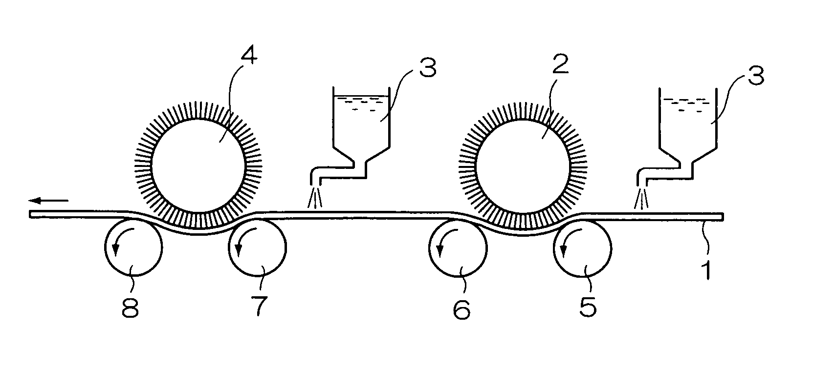
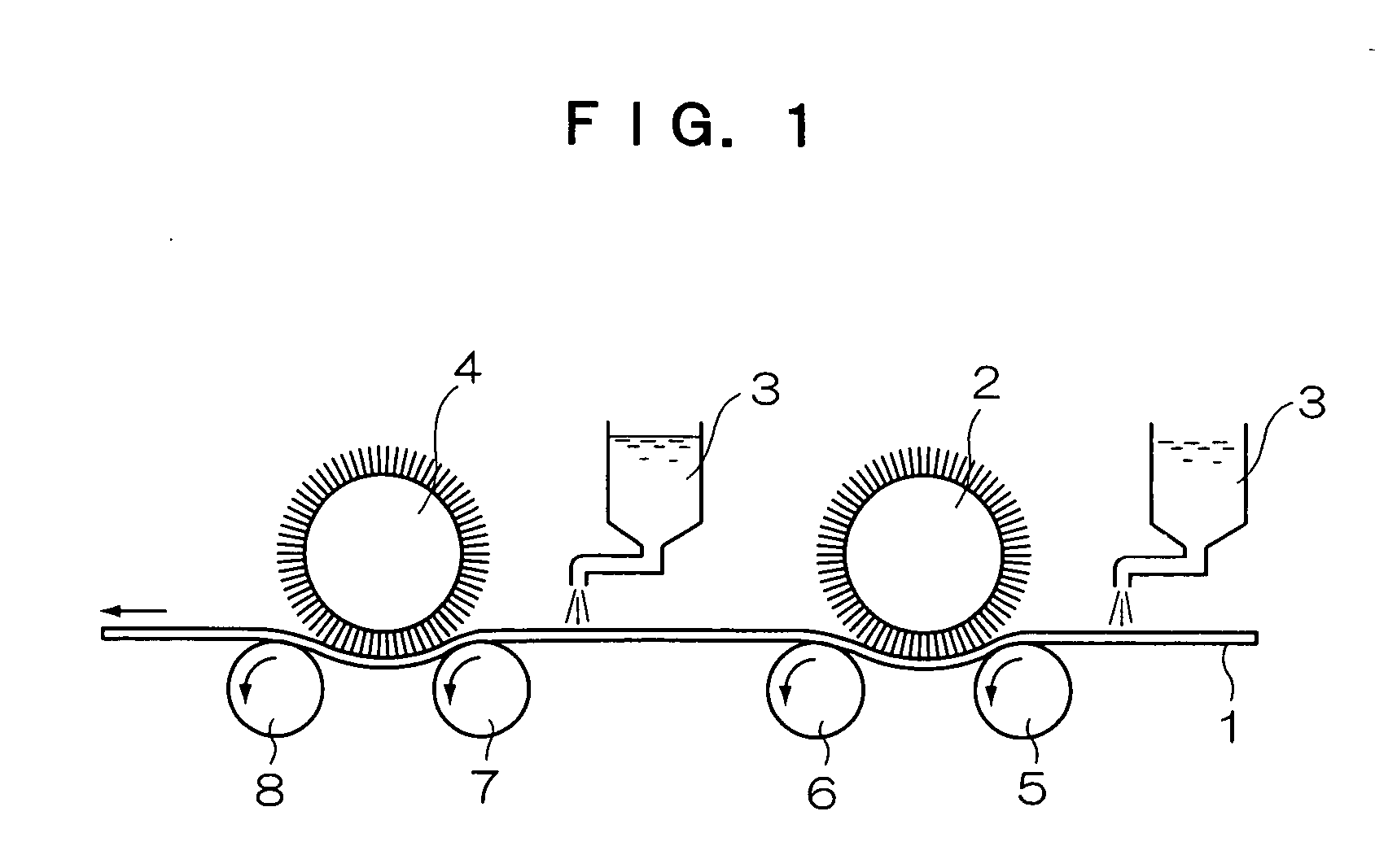
[Formation of Supports]

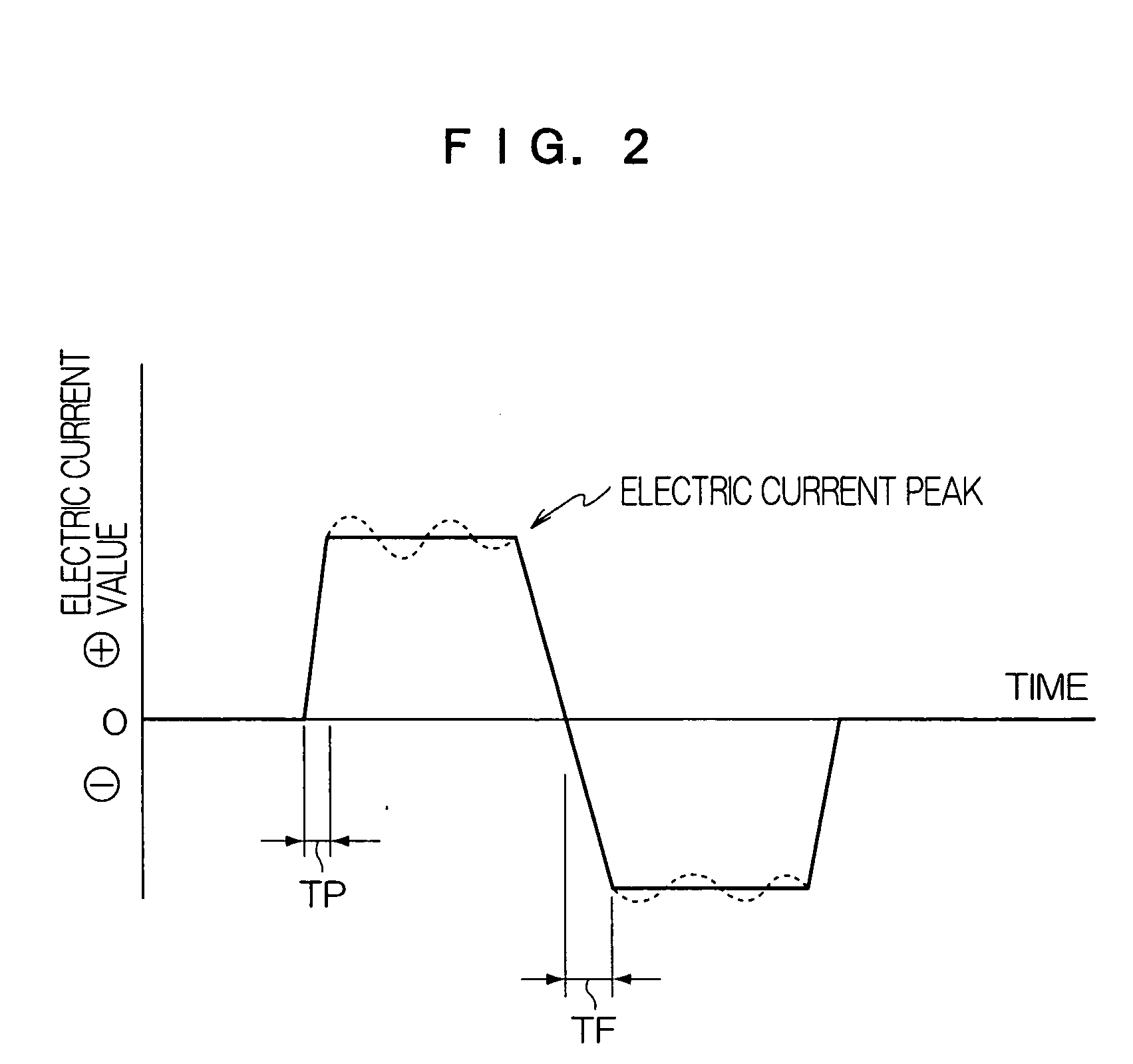
An aluminum plate (JIS A 1050 material) of 0.3 mm thickness was etched with an etching solution having a caustic soda concentration of 30 g / L and an aluminum ion concentration of 10 g / L (solution temperature: 60° C.) for 10 seconds, washed with flowing water, neutralized with a nitric acid solution having a nitric acid concentration of 10 g / L, and washed with water. An alternating current having a sine waveform was used to subject the aluminum plate to electrochemical surface-roughening treatment in an aqueous solution having a hydrogen chloride concentration of 15 g / L and an aluminum ion concentration of 10 g / L (solution temperature: 30° C.) at an applied voltage Va of 20 V and an electricity quantity of 500 C / dm2. The aluminum plate was washed with water, etched with an etching solution having a caustic soda concentration of 30 g / L and an aluminum ion concentration of 10 g / L (solution temperature: 40° C.) for 10 seconds, and washed with flowing water.

Nex...


PUM

PropertyMeasurementUnit
thicknessaaaaaaaaaa
thicknessaaaaaaaaaa
thicknessaaaaaaaaaa

Abstract

The present invention provides a planographic printing plate precursor including a support, and a recording layer which is formed on the support and includes a water-insoluble and alkali-soluble resin having active hydrogen in a main chain thereof and an infrared absorbent, the solubility of the recording layer in an aqueous alkaline solution being increased by exposure to light; and a planographic printing plate precursor including a support, and a recording layer formed on the support, wherein the recording layer includes a lower layer which is formed on the support and includes a water-insoluble and alkali-soluble resin having active hydrogen in a main chain thereof, and an upper layer which is formed on the lower layer and includes a water-insoluble and alkali-soluble resin and a development inhibitor, the solubility of the upper layer in an aqueous alkaline solution being increased by exposure to light, and at least one of the lower layer and the upper layer of the recording layer includes an infrared absorbent. According to the invention, there is provided is a positive planographic printing plate precursor which can provide a printing plate directly from scanning exposure based on digital signals and is excellent in printing durability and chemical resistance.

Description

CROSS-REFERENCE TO RELATED APPLICATION This application claims priority under 35 USC 119 from Japanese Patent Application No. 2003-337085, the disclosure of which is incorporated by reference herein. BACKGROUND OF THE INVENTION 1. Field of the Invention The present invention relates to a planographic printing plate precursor, and specifically to a positive type planographic printing plate precursor for the so-called “Computer To Plate (CTP)” system, from which a printing plate can directly be prepared on the basis of digital signals from a computer or the like. 2. Description of the Related Art In recent years, the development of lasers has been remarkable. In particular, among solid lasers and semiconductor lasers having an emission wavelength within near infrared and infrared wavelength ranges, small-sized ones having a high output have become readily available. In the field of planographic printing, these lasers are very useful as light sources for exposure, used to prepare ...

Claims


Application Information

Patent Timeline
Patent Type & Authority Applications(United States)
IPC IPC(8): B41C1/10G03F7/004G03F7/00G03F7/033G03F7/11
CPCB41C1/1008B41C1/1016B41C2201/04B41C2201/06B41C2201/10B41C2210/262B41C2210/02B41C2210/06B41C2210/14B41C2210/22B41C2210/24B41C2201/14
Inventor MAEMOTO, KAZUONAKAMURA, IPPEI
Owner FUJIFILM CORP
Why Eureka
Try Eureka