Hydrogen production method, hydrogen production apparatus, hydrogen supply facilities, nd method for generating electric power

a technology of hydrogen production apparatus and hydrogen supply, which is applied in the direction of gas dust removal, machine/engine, combustible gas production, etc., can solve the problems of increasing investment cost, generating carbon dioxide, and consuming fuel inevitably, so as to reduce running cost and facility cost , the effect of low cos

Inactive Publication Date: 2005-04-07
JFEENG CORP
View PDF2 Cites 19 Cited by
  • Summary
  • Abstract
  • Description
  • Claims
  • Application Information

AI Technical Summary

Benefits of technology

[0006] The present invention has been accomplished in order to overcome those disadvantages above. The object of the invention is to provide a method and an apparatus for producing hydrogen and a hydrogen supply plant. The method, apparatus, and plant perform hydrogen production, which requires high temperature, at a low cost using relatively low-temperature waste heat energy discharged from various types of heat processes, and the hydrogen production apparatus is so easy to start and suspend the operation as to reduce running cost and facility cost. Specifically, the present invention provides the following:

Problems solved by technology

This produces not only the problem of consuming fuel inevitably, but also the problem of generating carbon dioxide due to the combustion of the fuel.
In addition, since the reactor must maintain a constantly high-temperature field, it is required that at least the internal wall of the reactor is formed of expensive fire-resistant material, and consequently there occurs a problem that the investment cost becomes higher.
Accordingly, there occurs a problem that a large amount of energy loss happens, when the equipment starts or suspends the operation.
And there occurs a problem that the running cost of the equipment becomes higher.
The time consuming also becomes bigger.
Thus, it is undesirably difficult to operate the system only when it is required to supply the hydrogen.
And it is undesirably difficult to produce the hydrogen in accordance with a required small scale production or in accordance with a required short time production.
In addition, since the temperature in the reactor is maintained high over a long period from the startup time to the suspension time, the apparatus is required to be constituted of a large amount of refractories, and consequently the investment cost becomes undesirably higher.
Also, since natural gas or propane gas is used as a raw material, the running cost that is spent on the apparatus increases.
Therefore, from the standing point of preventing global warming, the above-mentioned emission, which has been a worldwide problem in the recent years, is unfavorable.

Method used


Image

  • Hydrogen production method, hydrogen production apparatus, hydrogen supply facilities, nd method for generating electric power
  • Hydrogen production method, hydrogen production apparatus, hydrogen supply facilities, nd method for generating electric power
  • Hydrogen production method, hydrogen production apparatus, hydrogen supply facilities, nd method for generating electric power

Examples


embodiment 1

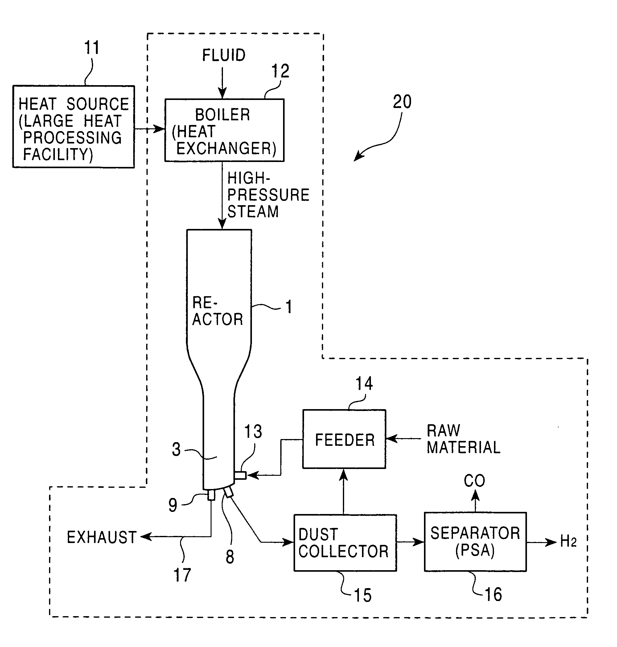
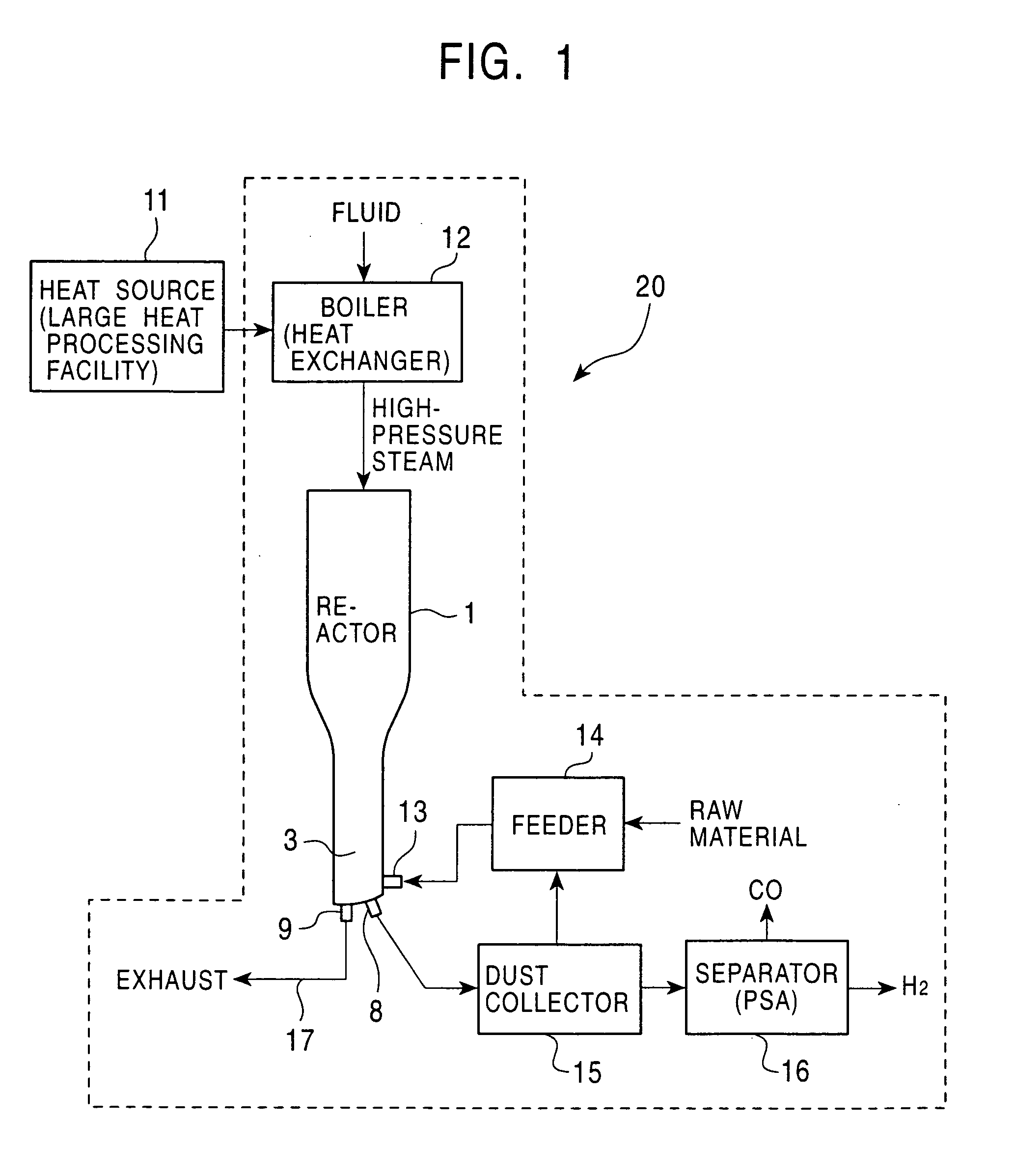
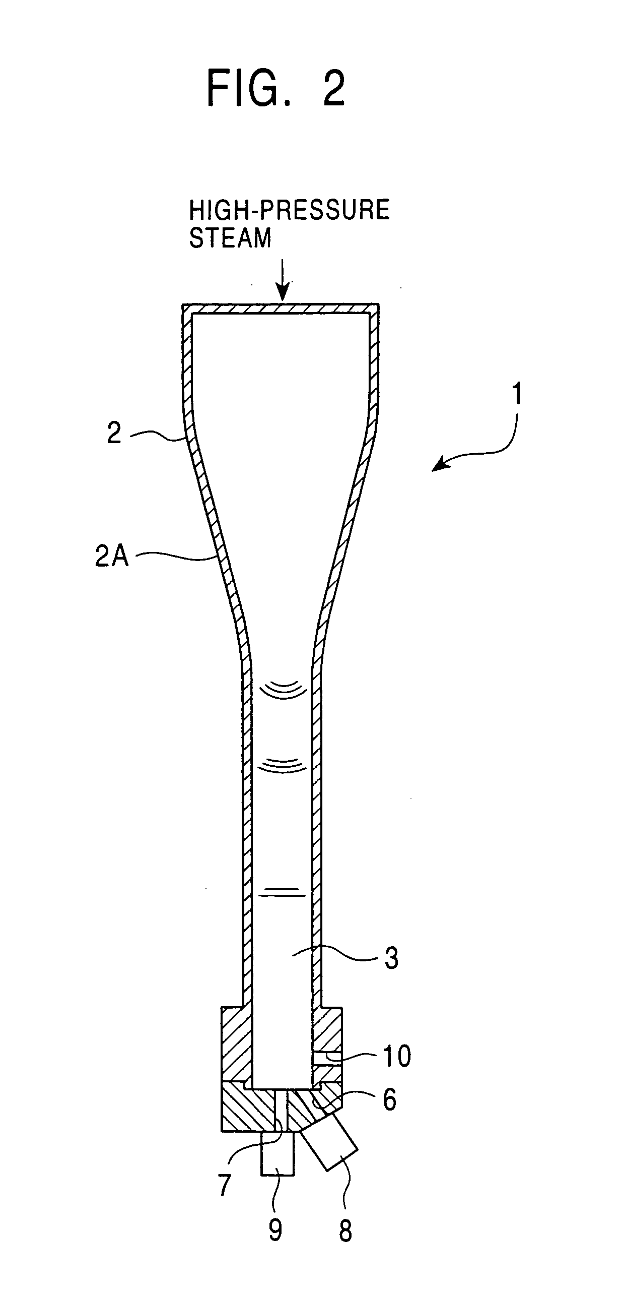
[0113]FIG. 1 is a structural block diagram of an apparatus for producing hydrogen according to Embodiment 1 of the present invention; and FIG. 2 is a sectional view of a reactor of the hydrogen production apparatus. In the figures, reference numeral 1 designates a reactor of a hydrogen production apparatus 20 conducting a reaction in which reactive particles containing hydrocarbon or carbon react with steam at a high temperature to produce hydrogen. The reactor includes a converging tube 2 having a converging portion 2A with a larger diameter at the upper end and a smaller diameter at the lower end and the cross section of the converging tube 2 thus decreases gradually from the upper end to the lower end. A space at the downstream side of the converging tube 2 defines a compression chamber 3 serving as a reaction chamber. High-pressure steam is instantaneously released to the converging tube 2 to generate shock waves, and the shock waves are converged in the converging portion 2A to...

embodiment 2

[0134]FIG. 4 is a structural block diagram of a hydrogen production apparatus according to Embodiment 2 of the present invention. In Embodiment 2, the boiler 12 being a heat exchanger of the hydrogen production apparatus 20 of Embodiment 1, which recovers the waste heat of exhaust gas from the heat source 11 and which heats a fluid (for example, water) to generate high-pressure steam by heat exchange, is replaced with a heater 12A which recovers the waste heat of exhaust gas from the heat source 11 and which heats a low-boiling-point fluid to generate high-pressure gas by heat exchange.

[0135] The low-boiling-point fluid has a boiling point lower than that of water, and may be LNG, LPG, liquefied carbon dioxide, ammonia, DME (dimethyl ether), an alcohol, or an ether. The low-boiling-point fluid itself may serve as a raw material of the reaction (hydrogen production) in some cases.

[0136] This structure provides substantially the same effects and advantages as Embodiment 1, and allow...

embodiment 3

[0137] In Embodiment 3 of the present invention, the hydrogen production apparatus 20 of Embodiment 1 is installed in a predetermined site to constitute a hydrogen supply plant, and is used as, for example, a hydrogen supply source for fuel-cell vehicles.

[0138] In the hydrogen supply plant having such a structure, when a fuel-cell vehicle comes in for feeding hydrogen, the hydrogen production apparatus 20 immediately starts operating to produce hydrogen and supply it into the tank of the vehicle. On completing hydrogen supply, the operation of the hydrogen production apparatus 20 is suspended. When another vehicle comes in, the hydrogen production apparatus 20 starts operation to supply hydrogen again as above.

[0139] Since the hydrogen production apparatus 20 is installed in a predetermined site to constitute a hydrogen supply plant, hydrogen is supplied to fill the object easily and immediately according to a demand for hydrogen, without providing an expensive hydrogen storage fa...


PUM

PropertyMeasurementUnit
temperatureaaaaaaaaaa

Abstract

A method and an apparatus for producing hydrogen and a hydrogen production plant are provided. In the method, hydrogen production requiring high temperature is performed at low cost using energy of relatively low-temperature exhaust heat discharged form various types of heat processes, and the apparatus can readily start and suspend operation and whose running cost and equipment cost are reduced. These are achieved by a method for producing hydrogen and a hydrogen production apparatus and plant for realizing the method. The method includes the step of heating a fluid to turn into a high-pressure gas having a pressure at least five times as high as the internal pressure of the hydrogen production apparatus before reaction by heat exchange with a heat source; the step of instantaneously releasing the high-pressure gas into the hydrogen production apparatus to generate a shock wave; the step of feeding a raw material into the hydrogen production apparatus before the generation of the shock wave; and the step of impact-compressing the raw material by the shock wave to heat the raw material, thereby producing hydrogen.

Description

TECHNICAL FIELD [0001] The present invention relates to a method for producing hydrogen and a hydrogen-containing fuel gas by subjecting a raw material, such as waste, to chemical reaction using a shock wave which is generated by instantaneously releasing a high-pressure gas prepared using relatively low-temperature waste heat energy discharged from various types of heat processes including waste incineration plants, and to an apparatus for producing hydrogen, a hydrogen supply plant, and a method for generating electric power by burning a hydrogen-containing gas. BACKGROUND OF THE INVENTION [0002] In order to produce hydrogen by reforming a wasted raw material with steam, an environment-conscious method (for example, Japanese Unexamined Patent Application Publication No. 2000-272904, pp. 3-4, FIG. 1, hereinafter referred to as “prior art 1”) may be applied to the hydrogen production process, which uses a heating furnace-type, double tube-type steam reforming reactor partitioned wit...

Claims


Application Information

Patent Timeline
Patent Type & Authority Applications(United States)
IPC IPC(8): C01B3/56C10J3/04C10J3/46C10J3/78
CPCC01B3/56C01B2203/043C01B2203/047C10J3/04C10J3/466C10K1/02C10J2300/0973C10J2300/0979C10J2300/1671C10J2300/1675C10J2300/1807C10J3/78Y02P20/129
Inventor SUZUKI, MINORUIWASAKI, KATSUHIRONAKAYAMA, TAKASHI
Owner JFEENG CORP
Why Eureka
Try Eureka