

Metal oxide nanotube and process for production thereof
a technology process, applied in the field of metal oxide nanotubes, can solve the problems of inability to perform the function repeatedly, inability to achieve the goal, and inability to use, and achieve the effect of high utility valu
- Summary
- Abstract
- Description
- Claims
- Application Information
AI Technical Summary
Benefits of technology
Problems solved by technology
Method used
Image

Examples
example 1
p-Dodecanoylamino phenyl glucopyranoside (3 mg) obtained in Production Example 1 and p-aminophenylglucopyranoside (3 mg) were dissolved in water-methanol mixed solvent (10:1, volume ratio, 1 ml) by heating the solution to 70° C. Next, tetraethoxysilane (20 mg) was added, and benzylamine (6 mg) was subsequently added.
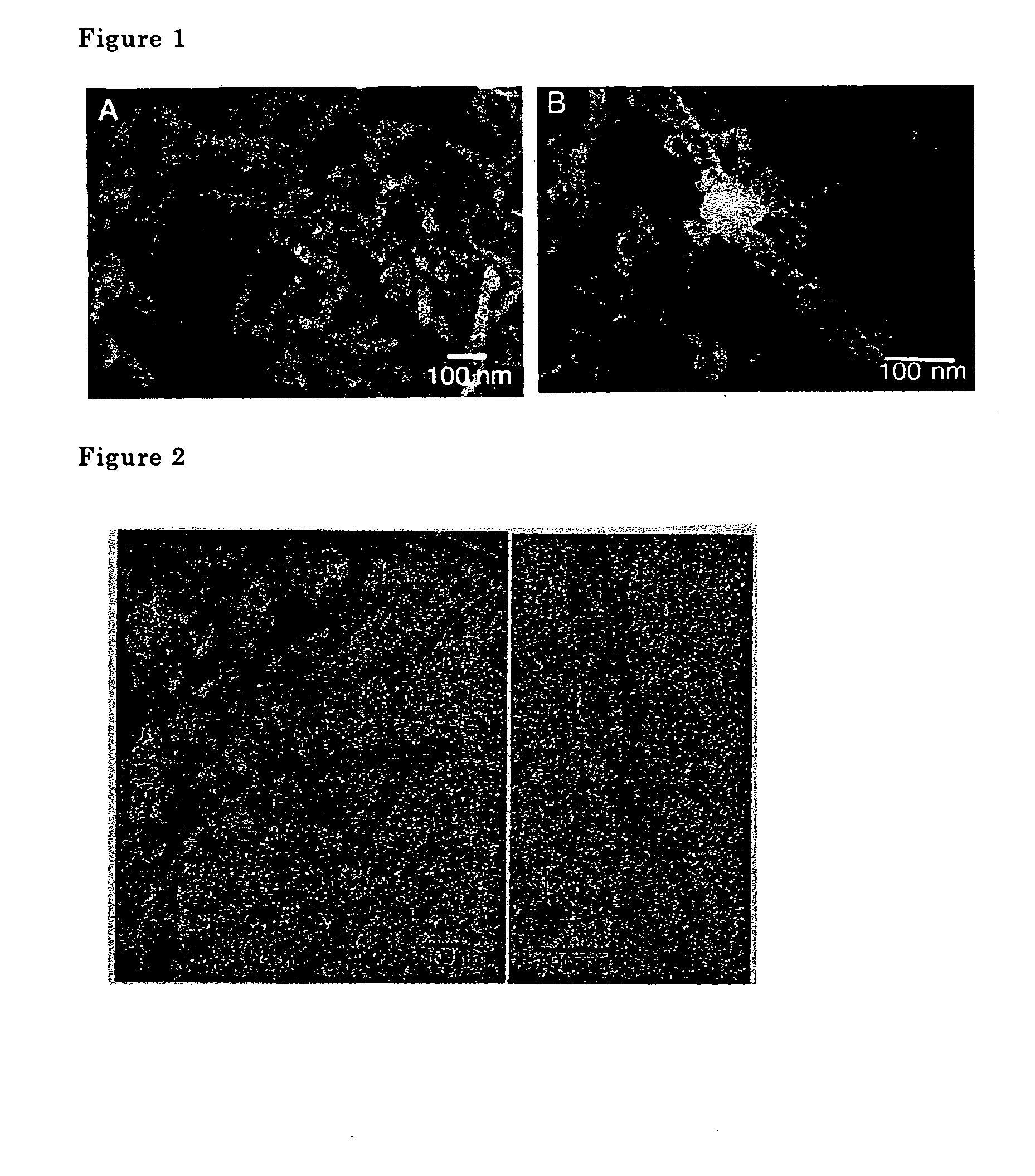
A gel was obtained through gradual cooling and was allowed to stand without any additional treatment for seven days at room temperature without agitation. The sample was sintered in a nitrogen gas atmosphere first for two hours at 200° C. and subsequently for four hours at 500° C. to completely remove the organic material. As a result, a metal oxide micro structure material (metal oxide nanotubes) was obtained.
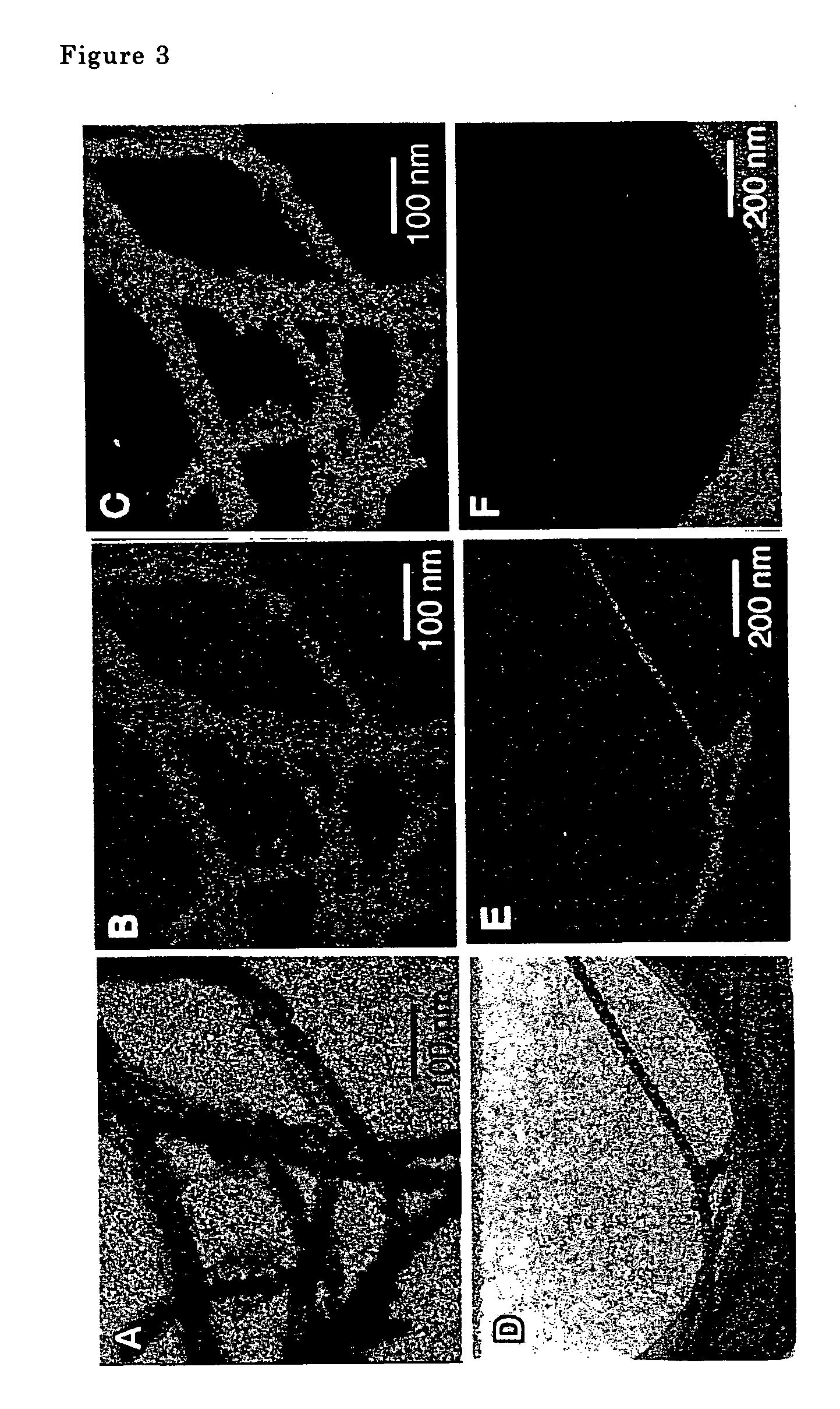
The metal oxide nanotubes were examined using a transmission type electron microscope. A scanning electron microscope photograph is shown in FIG. 1, a transmission electron microscope photograph is shown in FIG. 2. Double spiral shaped fibers comprising two na...
example 2
p-Dodecanoylamino phenylgalactopyranoside was used in place of p-dodecanoylamino phenylglucopyranoside in Example 1 and p-aminophenyl galactopyranoside was used in place of p-aminophenyl glucopyranoside to conduct the same operations described in Example 1, and similar double spiral silica nanotubes were obtained.
example 3
p-Tetradecanoylamino phenylglucopyranoside was used in place of p-dodecanoylamino phenylglucopyranoside in Example 1 to conduct the same operations described in Example 1, and, similarly, double spiral silica nanotubes were obtained.
PUM
| Property | Measurement | Unit |
|---|---|---|
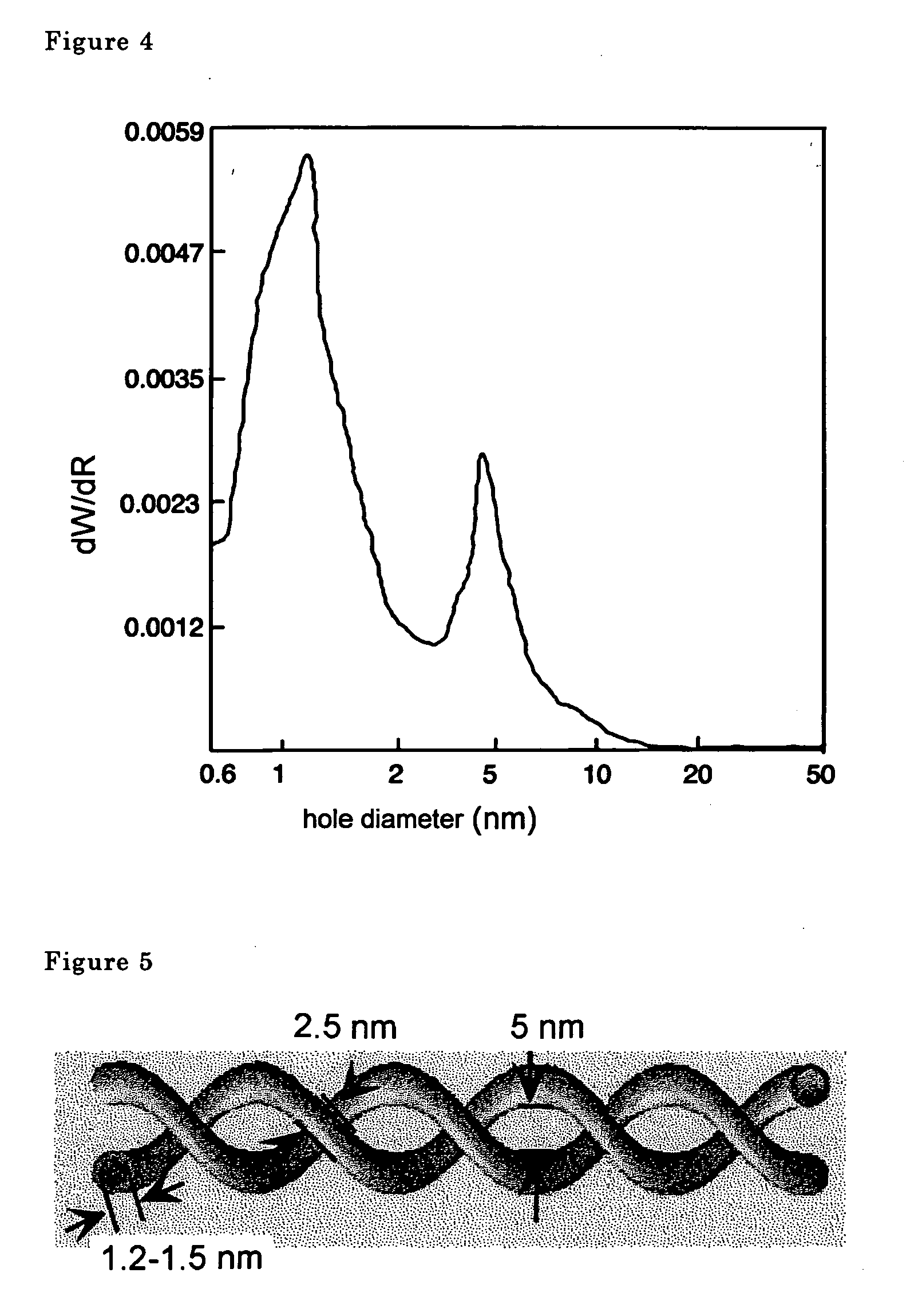
| hole diameters | aaaaa | aaaaa |
| hole diameters | aaaaa | aaaaa |
| hole diameters | aaaaa | aaaaa |
Abstract
Description
Claims
Application Information