

Metal halide lamp and lighting device
a technology of metal halide lamps and lighting devices, which is applied in the manufacture of electrode systems, electrode assemblies, electric discharge tubes/lamps, etc., can solve the problems that metal halide lamps without mercury cannot provide the advantage of thickening the discharge arc and the discharge arc is inevitably thin, so as to enhance the performance of metal halide lamps and increase the function of lamps
- Summary
- Abstract
- Description
- Claims
- Application Information
AI Technical Summary
Benefits of technology
Problems solved by technology
Method used
Image

Examples
embodiment
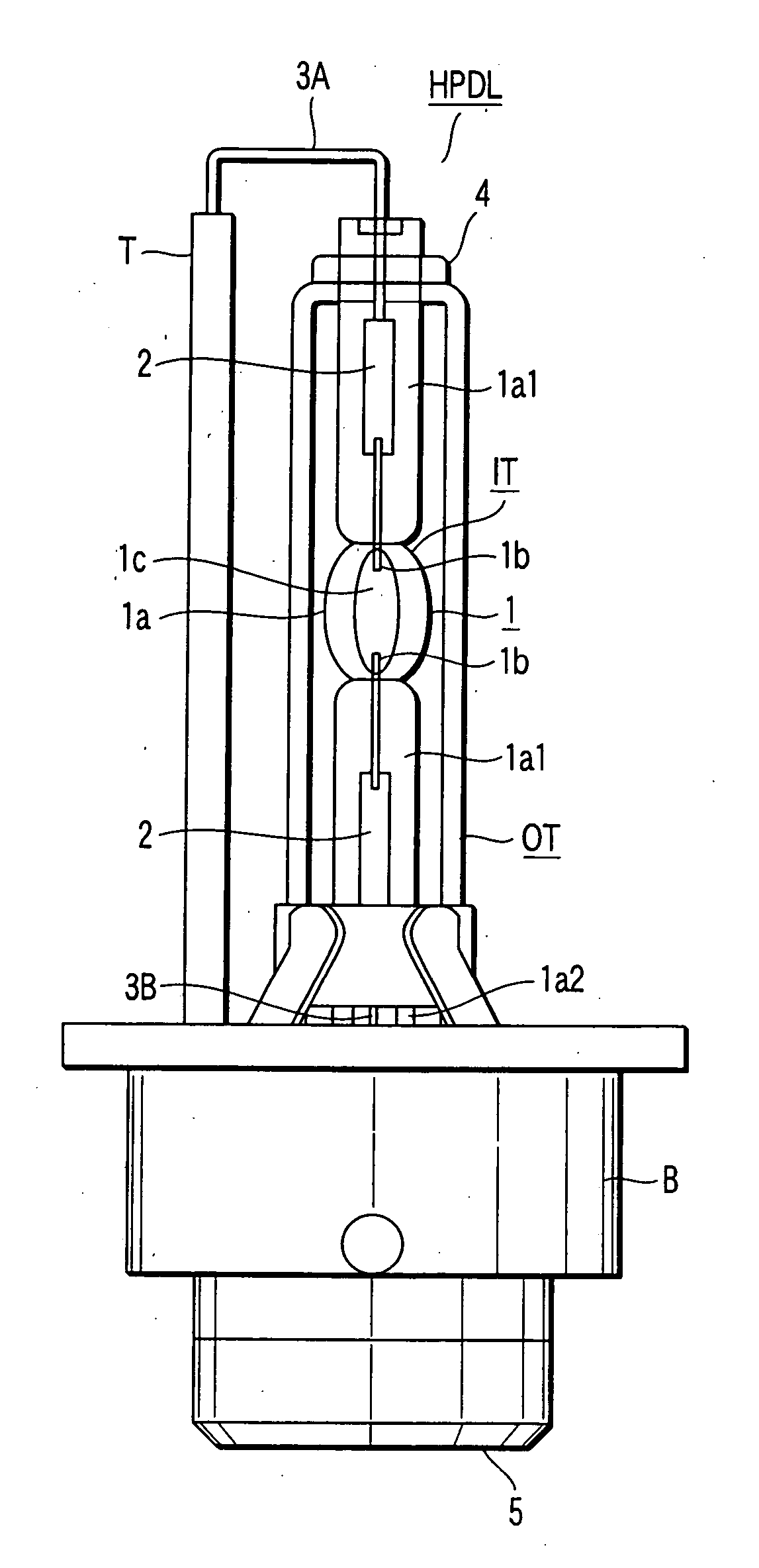
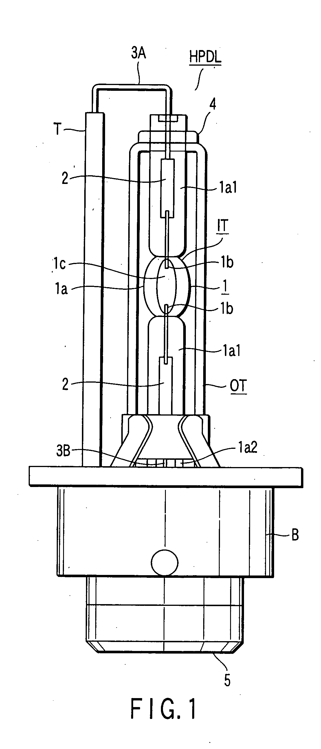
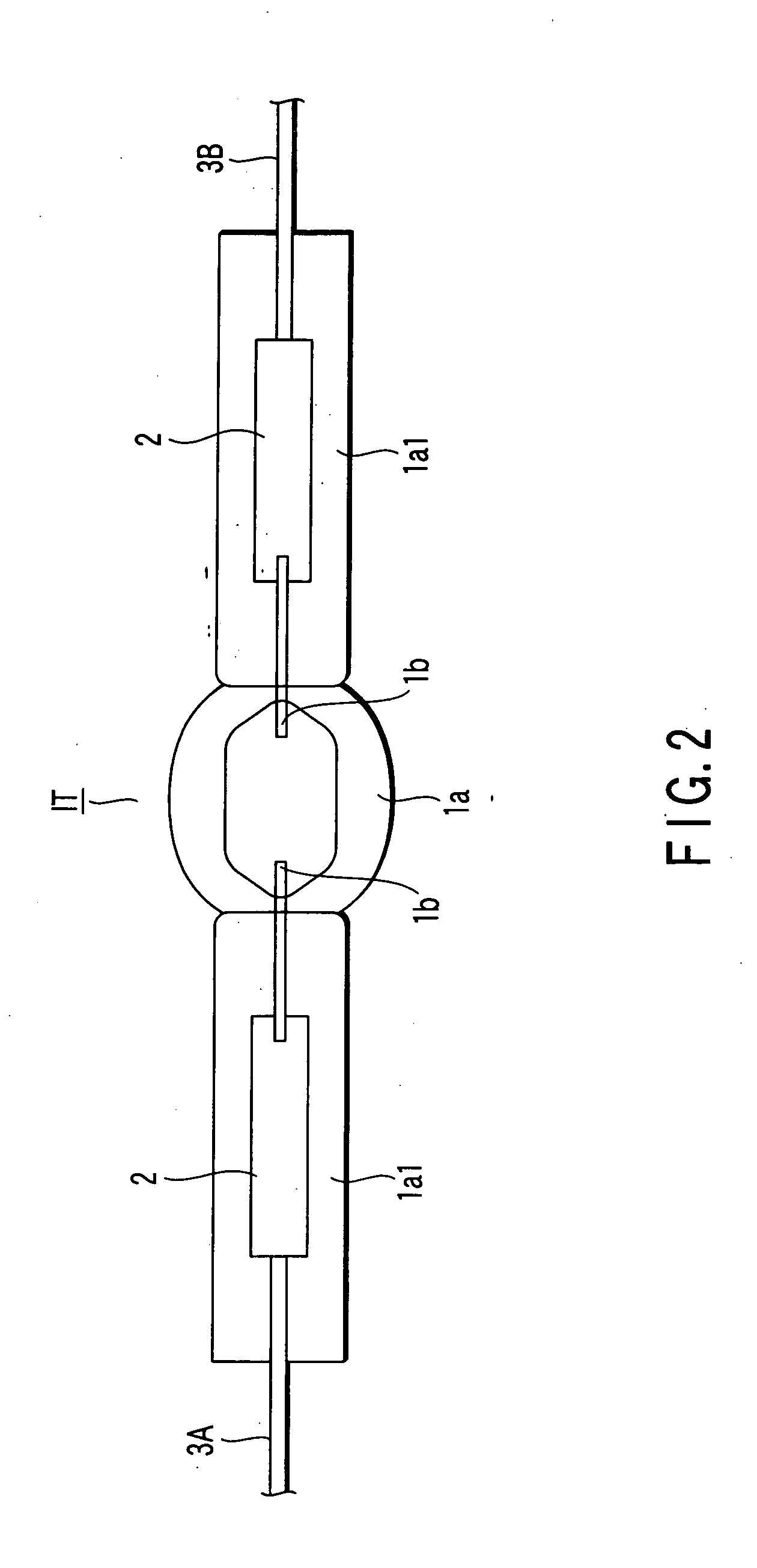
[0074] (Embodiment)
[0075] The embodiment of the invention shown in FIGS. 1 and 2 satisfies the following conditions: [0076] Light emission tube IT [0077] In airtight container 1a, material: quartz glass; internal volume: 0.025 cc; closing section maximum inner diameter: 2.6 mm; discharge space maximum length: 6.7 mm; maximum outer diameter: 6.0 mm [0078] In electrode 1b, material: doped tungsten; diameter: 0.32 mm; inter-electrode distance: 4.2 mm; [0079] Discharge medium [0080] Metal halide material: NaI-ScI3-InBr-ZnI2=0.3 mg [0081] Rare gas: Xenon of 11 atoms [0082] Outer tube OT [0083] Outer diameter: 9 mm; inner diameter: 7 mm; inner atmosphere: atmospheric pressure during lighting [0084] Power immediately after turn-on: 85 W [0085] Current immediately after turn-on: 2.8 A [0086] Lamp voltage in stable state: 42V [0087] Lamp current in stable state: 0.8 A [0088] Lamp power in stable state: 35 W [0089] Arc width: 1.05 mm.
[0090] Referring now to FIG. 3, a description will be give...
PUM
 Abstract
Description
Claims
Application Information