

Negative electrode for lithium metal battery and lithium metal battery comprising the same
a technology of lithium metal batteries and negative electrodes, which is applied in the direction of non-aqueous electrolyte cells, cell components, sustainable manufacturing/processing, etc., can solve the problems of increase the demand for electric vehicles, and short circuit between the positive electrode and the negative electrode, so as to improve the life cycle characteristics and prevent side reactions
- Summary
- Abstract
- Description
- Claims
- Application Information
AI Technical Summary
Benefits of technology
Problems solved by technology
Method used
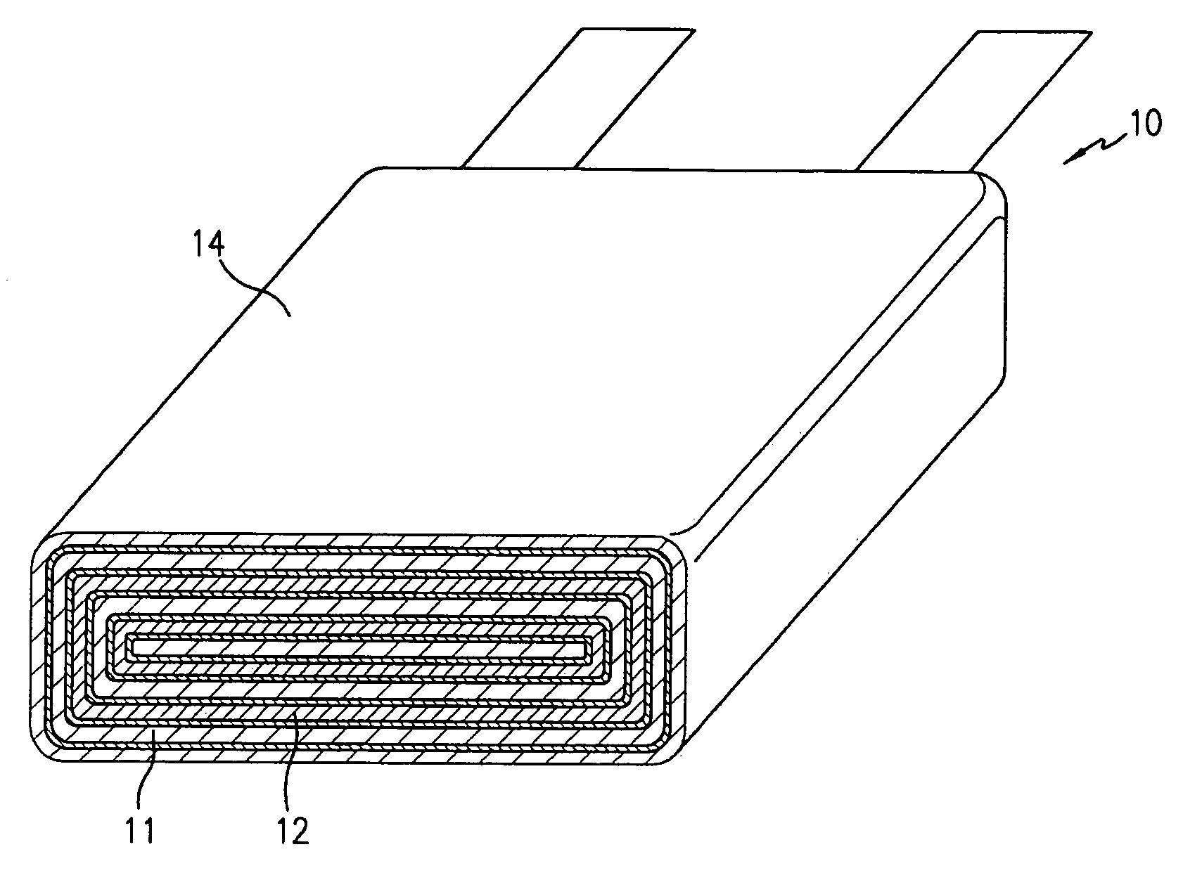
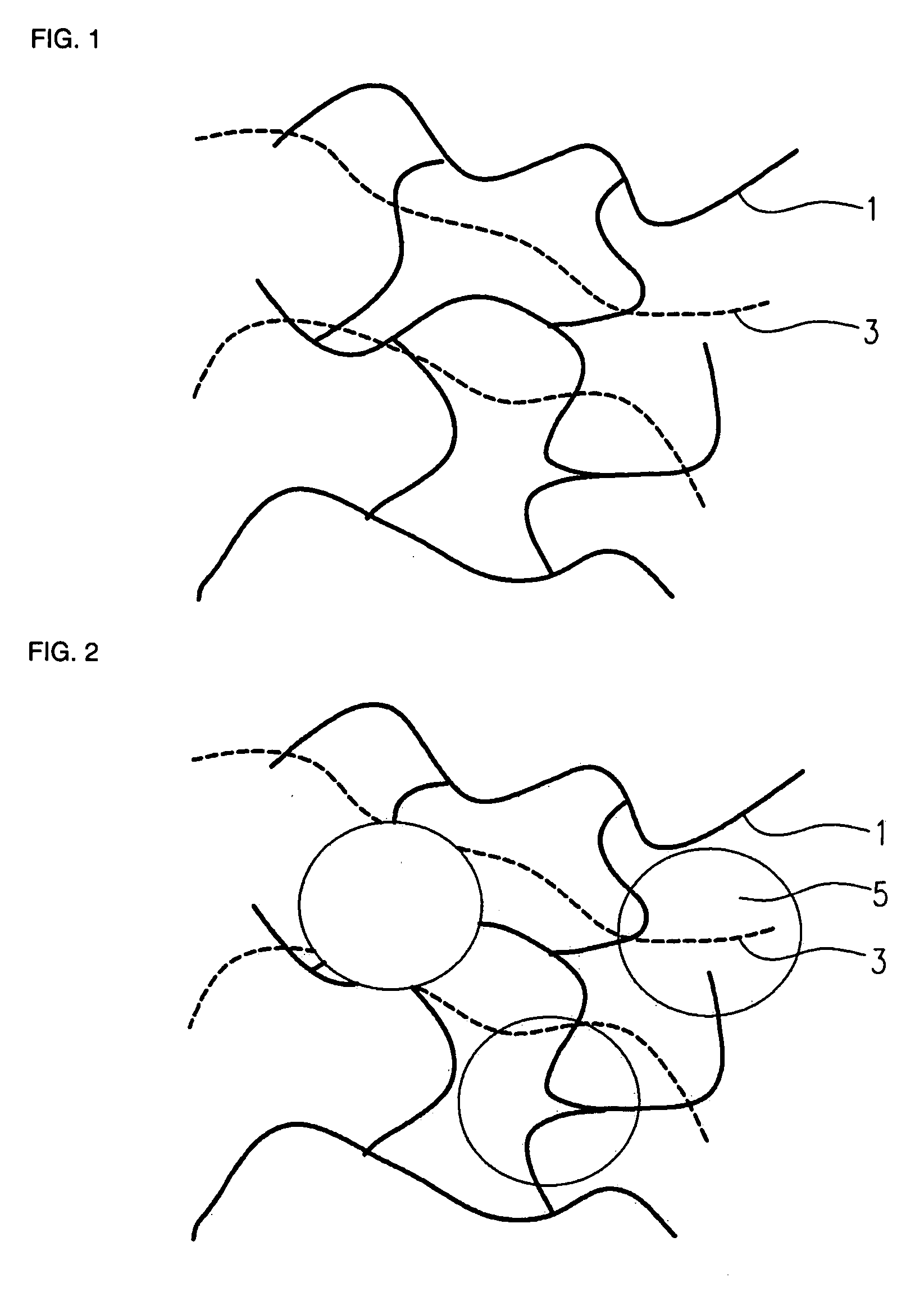
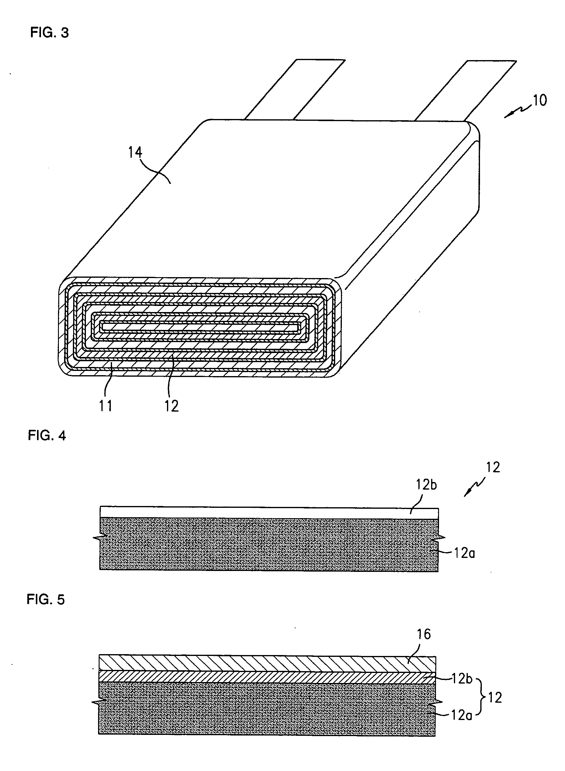
Image

Examples
example 1
[0082] A solution was prepared by dissolving 0.2 g of branched poly(ethylene oxide) (DAISO) having a weight-average molecular weight of 1,000,000 and 0.8 g of hexanediol diacrylate in 7.6 g of tetrahydrofuran. Then, 20 mg of azobisisobutyronitrile and 16 mg of phenylene dimaleimide were added and the solution was stirred for 10 minutes.
[0083] The resultant homogenous solution was applied on lithium which had been deposited to a thickness of 15 microns on a copper current collector, and coated using a spin coater operated at 1,000 rpm for 60 seconds. The lithium on which the passivation layer precursor film had been coated was heated at 80° C. for 2 hours under an argon atmosphere, so that the hexanediol diacrylate cross-linking monomers in the precursor were cross-linked. As a result, a passivation layer with a thickness of 1.2 microns was formed on the lithium electrode surface.
[0084] A lithium half cell was prepared using the lithium on which the passivation layer had been coate...
example 2
[0086] A solution was prepared by dissolving 0.4 g of polyvinyl chloride having a weight-average molecular weight of 100,000 and 0.6 g of hexanediol diacrylate in 15.2 g of tetrahydrofuran. Then, 20 mg of azobisisobutyronitrile were added and the solution was stirred for 10 minutes.
[0087] The resultant homogenous solution was applied on lithium which had been deposited to a thickness of 15 microns on a copper current collector, and coated using a spin coater operated at 1,000 rpm for 60 seconds. The lithium on which the passivation layer precursor film had been coated was heated at 80° C. for 2 hours under an argon atmosphere, so that the hexanediol diacrylate cross-linking monomers in the precursor were cross-linked. As a result, a passivation layer with a thickness of 1 micron was formed on the lithium electrode surface.
[0088] A lithium half cell was prepared using the lithium on which the passivation layer had been coated as a working electrode, and a lithium foil with a thickn...
example 3
[0091] A solution was prepared by dissolving 0.4 g of polyvinyl chloride having a weight-average molecular weight of 100,000, 0.6 g of hexanediol diacrylate, and 0.6 g of an inorganic single-ion conductor (inorganic particles) (OHARA) in 8.0 g of tetrahydrofuran. Then, 20 mg of azobisisobutyronitrile were added and the solution was stirred for 10 minutes.
[0092] The resultant homogenous solution was applied on lithium which had been deposited to a thickness of 15 microns on a copper current collector, and coated at 1,000 rpm for 60 seconds using a spin coater. The lithium on which the passivation layer precursor film had been coated was heated at 80° C. for 2 hours under an argon atmosphere, so that the hexanediol diacrylate cross-linking monomers in the precursor were cross-linked. As a result, a passivation layer with a thickness of 1.5 micron was formed on the lithium electrode surface.
[0093] A lithium half cell was prepared using the lithium on which the passivation layer had b...
PUM
 Abstract
Description
Claims
Application Information