Ultrasound transducers for imaging and therapy

Inactive Publication Date: 2005-05-05
OTSUKA MEDICAL DEVICES
View PDF81 Cites 253 Cited by
  • Summary
  • Abstract
  • Description
  • Claims
  • Application Information

AI Technical Summary

Benefits of technology

[0022] Another embodiment of the invention includes a plurality of transducer arrays, each directed toward a common focus point. Using multiple transducer arrays enables each array to contain fewer transducer elements and provides a relatively wide imaging and treatment field. Each transducer array may also be allowed to pivot about a pivot point, such that controlled pivoting of the multiple transducer arrays controls the location of the common focus point. This enables controlled movement of the common focus point in at least two directions.
[0023] Another aspect of the invention includes a transducer manufacturing method to produce an ultrasound transducer apparatus with a generally concave geometry. The method comprises the step of providing kerf fills having a non-uniform stiffness to control the curvature of the transducer array. For example, providing kerf fills with a symmetrically non-uniform stiffness improves the likelihood of obtaining a symmetric semi-circle shape of the array, rather than a parabolic shape

Problems solved by technology

High intensity focused ultrasound, which can have an intensity above 1000 watts per square centimeter, can raise the tissue temperature at the region of the spatial focus to above 60 degrees Celsius in a few seconds and can cause tissue necrosis almost instantaneously.
Often, however, the desire for high efficiency during ultrasound therapy and the desire for broad bandwidth during ultrasound imaging are difficult to satisfy simultaneously in the same transducer design.
The disadvantage of the electronic device is its complexity and associated relatively high cost.
However, system and transducer complexity is still one of the major disadvantages of electronic therapeutic arrays.
The thick cable required to meet this need makes the device difficult to handle.
Considering all these constraints, it will be evident that the complexity of such a therapeutic phased array, including the cable and the control system coupled to it, can easily become

Method used


Image

  • Ultrasound transducers for imaging and therapy
  • Ultrasound transducers for imaging and therapy
  • Ultrasound transducers for imaging and therapy

Examples


Example

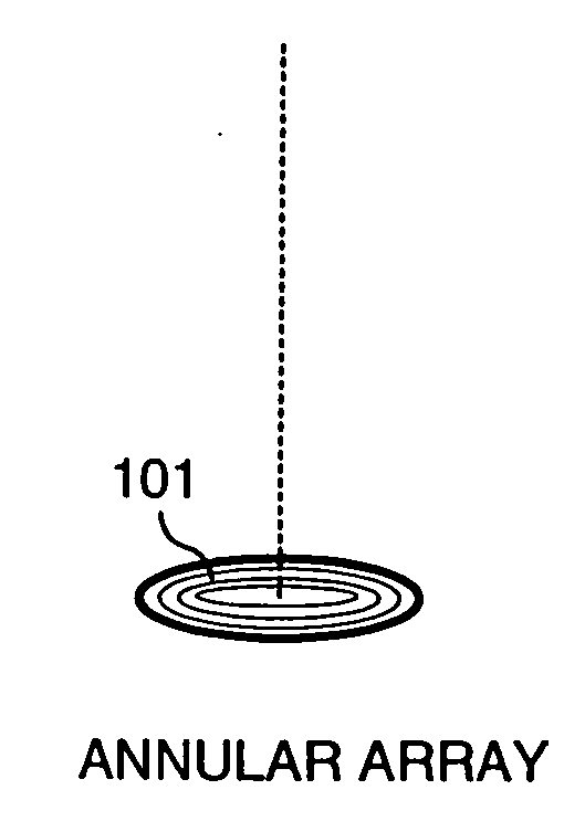
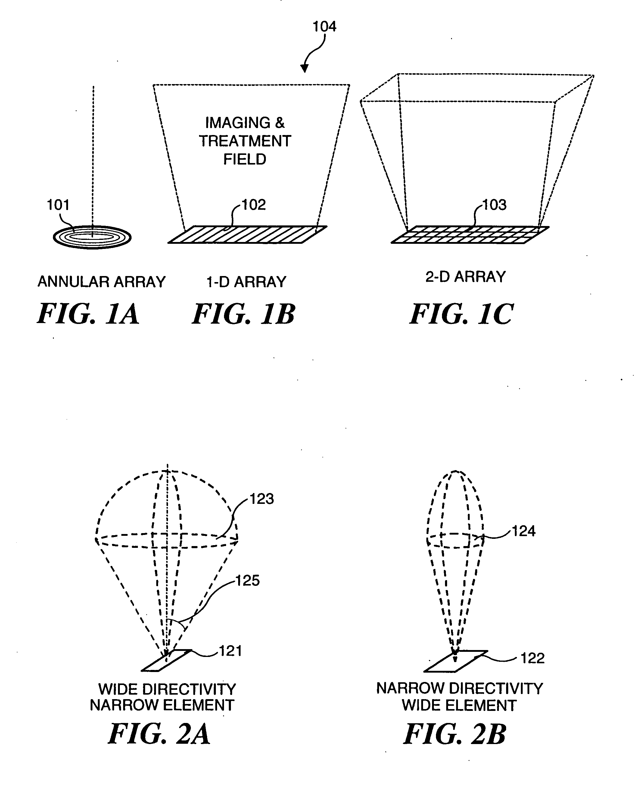
[0046] An ultrasound array includes many small transducer elements on its aperture surface, and these transducer elements can be distributed in several different geometric arrangements, as shown in FIGS. 1A-1C. Each transducer element is independently driven by its own electronic circuitry. An annular array (FIG. 1A) includes many coaxial ring elements 101. A one-dimensional (1-D) array (FIG. 1B) includes many elongate row elements 102 arranged side-by-side and extending transversely across the longitudinal axis of the array. A 1½-D or two-dimensional (2-D) array (FIG. 1C) includes a matrix of elements 103 distributed over two dimensions. The 1-D array has the advantage of simplicity and is therefore a preferred configuration for use in the present invention. The same advantages of the invention described herein can also be achieved using 1½-D and 2-D arrays. The 1-D array has a 2-D imaging and treatment field 104, or plane that extends along the longitudinal axis of the array.

[004...


PUM


Abstract

Ultrasound applicators able to both image a treatment site and administer ultrasound therapy include an array of transducer elements that can be focused. In several embodiments, an electronically phased array is used for controlling the focal point of an ultrasound beam. The ultrasound beam produced thereby can also be electronically steered. To reduce the quality factor or Q of the array when the array is used for imaging, an electronic switch is selectively closed, placing a resistance in parallel with each of the array elements. A flexible array is employed in several embodiments and is selectively bent or flexed to vary its radius of curvature and thus control the focal point and/or a direction of focus of the array. In another embodiment, each of the transducer elements comprising the array are individually mechanically pivotable to steer the ultrasonic beam produced by the transducer elements.

Description

RELATED APPLICATIONS [0001] This application is based on U.S. provisional patent application, Ser. No. 60 / 171,703, filed Dec. 23, 1999, the benefit of the filing date of which is hereby claimed under 35 U.S.C. §119(e).FIELD OF THE INVENTION [0002] The present invention generally relates to use of ultrasound for imaging and therapeutic purposes, and more specifically, to simplified ultrasound transducers that are both highly efficient for administering therapy and produce a wide bandwidth ultrasound signal for diagnostic imaging. BACKGROUND OF THE INVENTION [0003] Ultrasound is a term that refers to acoustic waves having a frequency above the upper limit of the human audible range (i.e., above 20 kHz). Because of their relatively short wavelength, ultrasound waves are able to penetrate into the human body. Based on this property, ultrasound in the frequency range of 2-20 MHz has been widely used to image internal human organs for diagnostic purposes. [0004] To avoid thermal damage to...

Claims


Application Information

Patent Timeline
IPC IPC(8): A61B8/12A61B19/00A61B17/00A61B17/22A61B17/225A61B18/00A61H23/02A61N7/02G10K11/32G10K11/34H04R17/00
CPCA61B17/0057A61B8/445A61B2017/00907A61B2019/462A61B2019/5276A61B2019/5404A61B2019/5437A61B2562/164A61H23/0245A61N7/02A61N2007/0052A61N2007/0065A61N2007/0078G10K11/32G10K11/346A61B8/12A61B8/4461A61B2017/00504A61B2090/3904A61B2090/062A61B2090/378A61B2090/3937
Inventor WENG, LEEPEROZEK, DAVID M.ZHANG, JIMIN
Owner OTSUKA MEDICAL DEVICES
Why Eureka
Try Eureka