Aerogel/PTFE composite insulating material

a composite insulation material and aerogel technology, applied in the field of materials, can solve the problems of low thermal conductivity, low thermal conductivity, and low thermal conductivity of air conducting heat, and achieve the effects of high sound absorption coefficient, good sound absorption, and high sound transmission loss

Active Publication Date: 2005-05-12
WL GORE & ASSOC INC
View PDF5 Cites 152 Cited by
  • Summary
  • Abstract
  • Description
  • Claims
  • Application Information

AI Technical Summary

Benefits of technology

[0009] Materials of the present invention comprise aerogel particles and polytetrafluoroethylene (PTFE) as a binder. Preferred materials may be formed having a consistency or texture of powder or putty, and also may be formed into shaped structures having good mechanical strength and flexibility. Properties of the shaped structures, such as mechanical strength and thermal conductivity may be affected partly by the relative proportions of the aerogel and PTFE. For example, higher proportions of aerogel particles typically result in lower thermal conductivity and higher proportions of PTFE typically result in a structure with greater mechanical strength.

Problems solved by technology

Because of the small pore size, the mobility of air molecules within the material is restricted, and the effectiveness of air in conducting heat is reduced, resulting in low thermal conductivity.
Aerogel powders and beads are known to have a thermal conductivity of about 9 to 20 mW / m K. However, such highly porous and low density material is not useful for many applications in the form of a powder due to the extensive dusting which makes installation, handling, forming and shaping particularly difficult, and further raises safety issues.
Processes, such as those using supercritical fluid extraction, are very time consuming and expensive.
Further, the structures produced are rigid and have low mechanical strength and have limited ability to be further molded or formed into desired shapes after the aerogel material is formed.
These materials often crack or shatter upon flexing and are known for shedding or “dusting” of fine aerogel particles.
However, applications for such materials are limited due to a lack of moldability and formability of these structures, as well as the costs associated with supercritical extraction steps.
However, in the form of a powder, aerogel is not useful for many applications due to high dusting and lack of formability.

Method used


Image

  • Aerogel/PTFE composite insulating material
  • Aerogel/PTFE composite insulating material
  • Aerogel/PTFE composite insulating material

Examples


example 1

[0060] A non-dusting material putty was made comprising about 80% wt aerogel particles and about 20% wt PTFE.

[0061] A 4.37% wt dispersion containing about 0.8 kg of hydrophobic, surface treated powder of silica aerogel (Nanogel aerogel, grade OJ0008, Cabot Corp., Billerica, Mass.), jet-milled to a particle size of about 7 μm, was made in a 25 liter container by adding about 8.75 kg of isopropyl alcohol (VWR International Inc., Bridgeport, N.J.) and 8.75 kg of de-ionized water while agitating at 750 rpm for about 5 minutes. The agitation speed was then increased to 1500 rpm. About 0.2 kg of PTFE particles in dispersion, as 0.875 kg of a 23% wt polytetrafluoroethylene aqueous dispersion (TEFRMS 153, DuPont, Wilmington, Del.), was rapidly poured into the mixing vessel. Immediately after, about 0.5 kg of 0.4% wt Sedipure surfactant solution (CF803, Tensid-Chemie Vertriebsgesellschaft mbH, BASF Group, Koeln, Germany) was poured into the mix. The total of the solids in the slurry was abo...

example 2

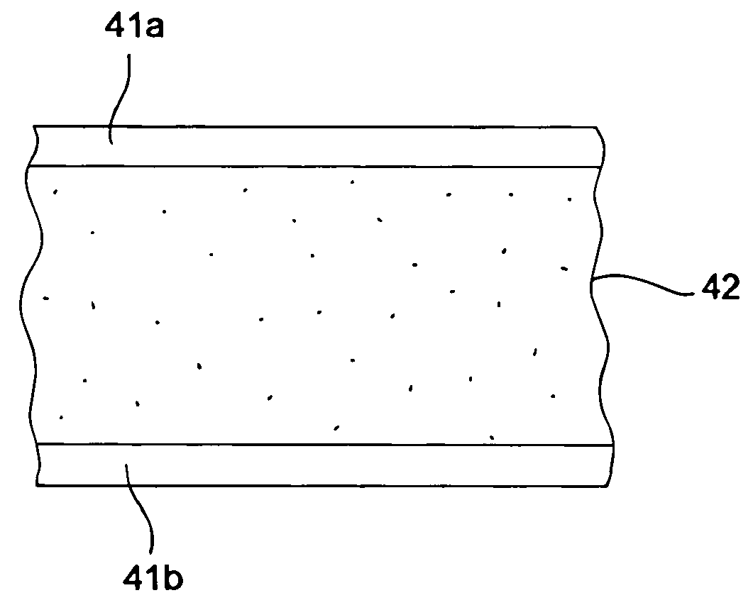
[0064] An insulating composite was prepared having a core material comprising 80% wt aerogel and 20% wt PTFE within an envelope of ePTFE membrane.

[0065] The material of Example 1, was poured into a rectangular mold having dimensions of 12 cm×13.3 cm×0.8 cm and slightly compressed into a putty. The mold containing the putty was placed between the two layers of aluminized plastic foil. The mold was removed leaving the molded putty between the two layers of the foil. Three sides of the foil around the molded putty were sealed using a hot iron to form an envelope. The envelope containing the putty was transferred into a vacuum packing machine, and the fourth edge of the envelope was sealed under vacuum of 1.5 kPa.

[0066] The final vacuum packed form was very flexible, did not form any cracks or edges upon flexing, and had an overall thickness of 7.12 mm and thermal conductivity of 9.55 mW / m K when measured substantially according to the test for Thermal Conductivity Measurements (Test ...

example 3

[0067] An insulating structure was made from a material comprising about 80% wt aerogel and about 20% wt PTFE.

[0068] In a 75.7 liter open mixing vessel, about 29.2 kg of de-ionized water was added to about 29.2 kg. of isopropyl alcohol (VWR International, Inc., Bridgeport, N.J.). To this, about 2.68 kg of hydrophobic, surface treated silica aerogel (Nanogel aerogel, grade OJ0008 from Cabot Corp., Billerica, Mass.; jet-milled to a particle size of about 7 μm) was added. Using a standard propeller type impeller, the whole mix was agitated at 1500 rpm for four (4) minutes and then at 1000 rpm for another four (4) minutes to obtain a uniform slurry. To this slurry, about 0.68 kg of PTFE solids was added in the form of dispersion (TEFRMS 153, DuPont, Wilmington, Del.) containing about 26.3% by weight solids. The mix was agitated at 1000 rpm for one (1) minute to coagulate the PTFE in presence of silica aerogel. The coagulum was filtered, dried, chilled and screened into a granular powde...


PUM

PropertyMeasurementUnit
thermal conductivityaaaaaaaaaa

Abstract

A material comprising aerogel particles and a polytetrafluoroethylene (PTFE) binder is formed having a thermal conductivity of less than or equal to 25 mW / m K at atmospheric conditions. The material is moldable or formable, having little or no shedding of filler particles, and may be formed into structures such as tapes or composites, for example, by bonding the material between two outer layers. Advantageously, composites may be flexed, stretched, or bent without significant dusting or loss of insulating properties.

Description

BACKGROUND OF THE INVENTION [0001] The present invention relates to a material that is useful in multiple applications including insulation applications for garments, containers, pipes, electronic devices and the like. Among other things, the material of the present invention comprising aerogel particles and polytetrafluoroethylene (PTFE), is formable, having low particle shedding and low thermal conductivity. Composites made from the material may be flexed, stretched, and twisted, with little or no shedding of aerogel particles or loss of conductive properties. [0002] Use of aerogels for thermal insulation and the low thermal conductivity of aerogels is well known. Favorable thermally conductive properties result from the very high porosity of aerogel which is greater than about 95%, and the small pore size of aerogel material which is less than the size of the mean free path of air molecules at atmospheric pressure, or less than about 100 nm. Because of the small pore size, the mo...

Claims


Application Information

Patent Timeline
Patent Type & Authority Applications(United States)
IPC IPC(8): B32B27/08B32B27/18C08K3/22C08K3/36H05K1/03
CPCA41D19/01529B29C66/727B29C65/48B29C66/001B29C66/45B29C66/71B29C66/731B29C66/73113B29C66/82661B29K2021/003B29K2027/18B29K2067/00B29K2069/00B29K2075/00B29K2077/00B29K2083/00B29K2105/0085B29K2995/0015B29K2995/0065B29K2995/0092B29L2009/00B29L2023/225B29L2031/3431B29L2031/4864B32B15/08B32B27/08B32B27/18B32B2307/304B32B2327/18C08K3/22C08K3/36F16L59/028G06F1/203H01L23/433H04M1/0214H04M1/026H05K1/034H05K1/0373B29C63/08Y10T428/25H01L2924/0002B29C66/729F28F2270/00C08L27/18H01L2924/00B29C66/721Y10T428/31544Y10T428/31551Y10T428/31786Y10T428/31725Y10T428/31678Y10T428/249924B32B5/18B32B2260/00B32B2405/00B32B2307/206B32B2307/7242B32B2307/7265B32B7/12B32B15/20
Inventor RISTIC-LEHMANN, CEDOMILAFARNWORTH, BRIANDUTTA, ANITREIS, BRADLEY E.
Owner WL GORE & ASSOC INC
Why Eureka
Try Eureka