Erosion resistant coatings and methods thereof

a technology of erosion resistance and coating, applied in the direction of machines/engines, waterborne vessels, natural mineral layered products, etc., can solve the problems of hydroelectric turbine components, hydroelectric turbine components, and hydroelectric turbine components that have not been found to have significant erosion resistance,

Active Publication Date: 2005-05-26
GENERAL ELECTRIC CO
View PDF17 Cites 38 Cited by
  • Summary
  • Abstract
  • Description
  • Claims
  • Application Information

AI Technical Summary

Benefits of technology

[0010] Disclosed herein are erosion resistant coatings and processes, which are especially suitable for coating hydroelectric turbine components that are exposed to silt during operation thereof. In one embodiment, the erosion resistant coating comprises a matrix comprising cobalt chromium and a plurality of tungsten carbide grains embedded in the cobalt chromium matrix, wherein the grains are less than about 2 microns in diameter, wherein the cobalt is at about 4 to about 12 weight percent, and the chromium is at about 2 to about 5 weight percent, wherein the weight percents are based on a total weight of the coating.

Problems solved by technology

Existing base materials for hydroelectric turbine components such as martensitic stainless steels do not have adequate erosion resistance under these conditions.
For example, hydroelectric turbine components when exposed to silt in the rivers that exceed 1 kg of silt per cubic meter of water have been found to undergo significant erosion.
This problem can be particularly severe in Asia and South America where the silt content during the rainy season can exceed 50 kg of silt per cubic meter of water.
The severe erosion that results damages the turbine components causing frequent maintenance related shutdowns, loss of operating efficiencies, and the need to replace various components on a regular basis.
However, current compositions of the above noted materials and processes used to apply them generally yield coatings that are not totally effective during prolonged exposure to silt.
One limitation to current thermal spray processes is the limited coating thicknesses available due to high residual stress that results as thickness is increased by these methods.
As a result, the final coating is relatively thin and fails to provide prolonged protection of the turbine component.
Other limitations of these thermal spray processes are the oxidation and decomposition of the powder feed or wire feed stock during the coating process that form the anti-erosion coating, which can affect the overall quality of the finished coating.
These thermal spray processes generally leave the resulting coating with relatively high porosity, high oxide levels, and / or tends to decarborize primary carbides, if present in the coating.
All of these factors have significant deleterious effects at reducing erosion resistance of the coatings.
However, even HVOF yields coatings with high residual stress, which limits the coating thickness to about 500 microns (0.020 inches) in thickness.
Also, because of the gas constituents used in the HVOF process and resulting particle temperature and velocity, the so-formed coatings generally contain high degrees of decarburization, which significantly reduces the coating erosion resistance.
This is true because a crack in a well-bonded coating may propagate into the substrate, initiating a fatigue-related crack and ultimately cause a fatigue failure.
Unfortunately, most thermal spray coatings have very limited STF, even if the coatings are made from pure metals, which would normally be expected to be very ductile and subject to plastic deformation rather than prone to cracking.
Moreover, it is noted that thermal spray coatings produced with low or moderate particle velocities during deposition typically have a residual tensile stress that can lead to cracking or spalling of the coating if the thickness becomes excessive.
Although high compressive stresses can beneficially affect the fatigue characteristics of the coated component, high compressive stresses can, however, lead to chipping of the coating when trying to coat sharp edges or similar geometric shapes.

Method used


Image

  • Erosion resistant coatings and methods thereof
  • Erosion resistant coatings and methods thereof
  • Erosion resistant coatings and methods thereof

Examples


Embodiment Construction

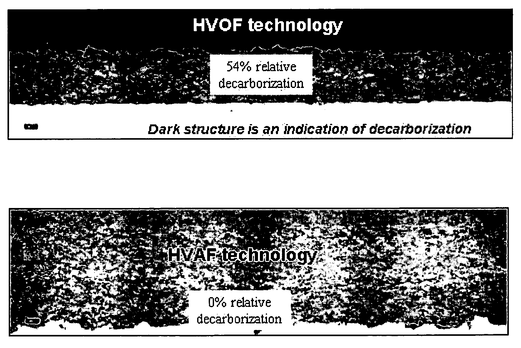
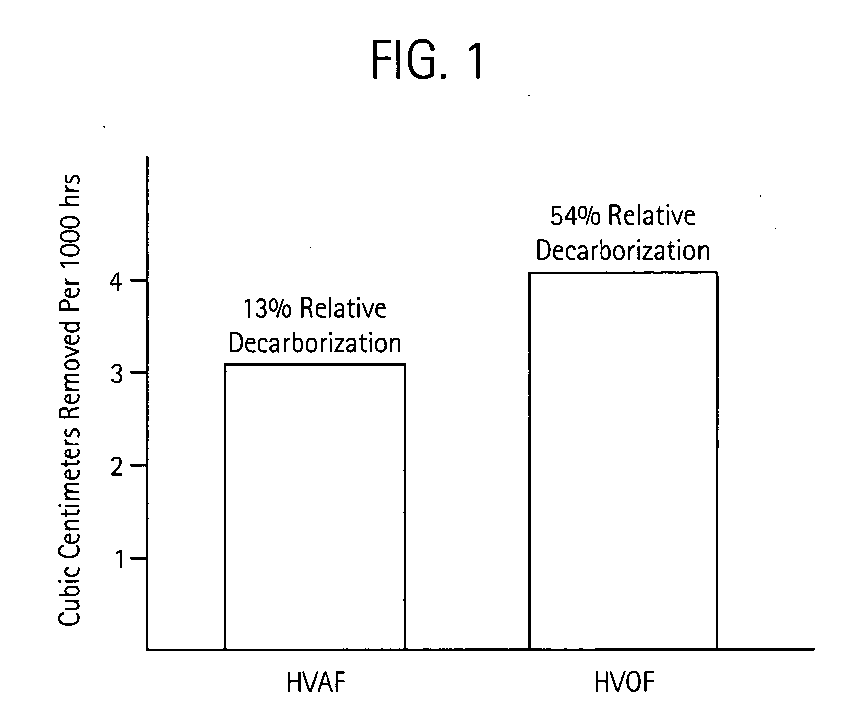
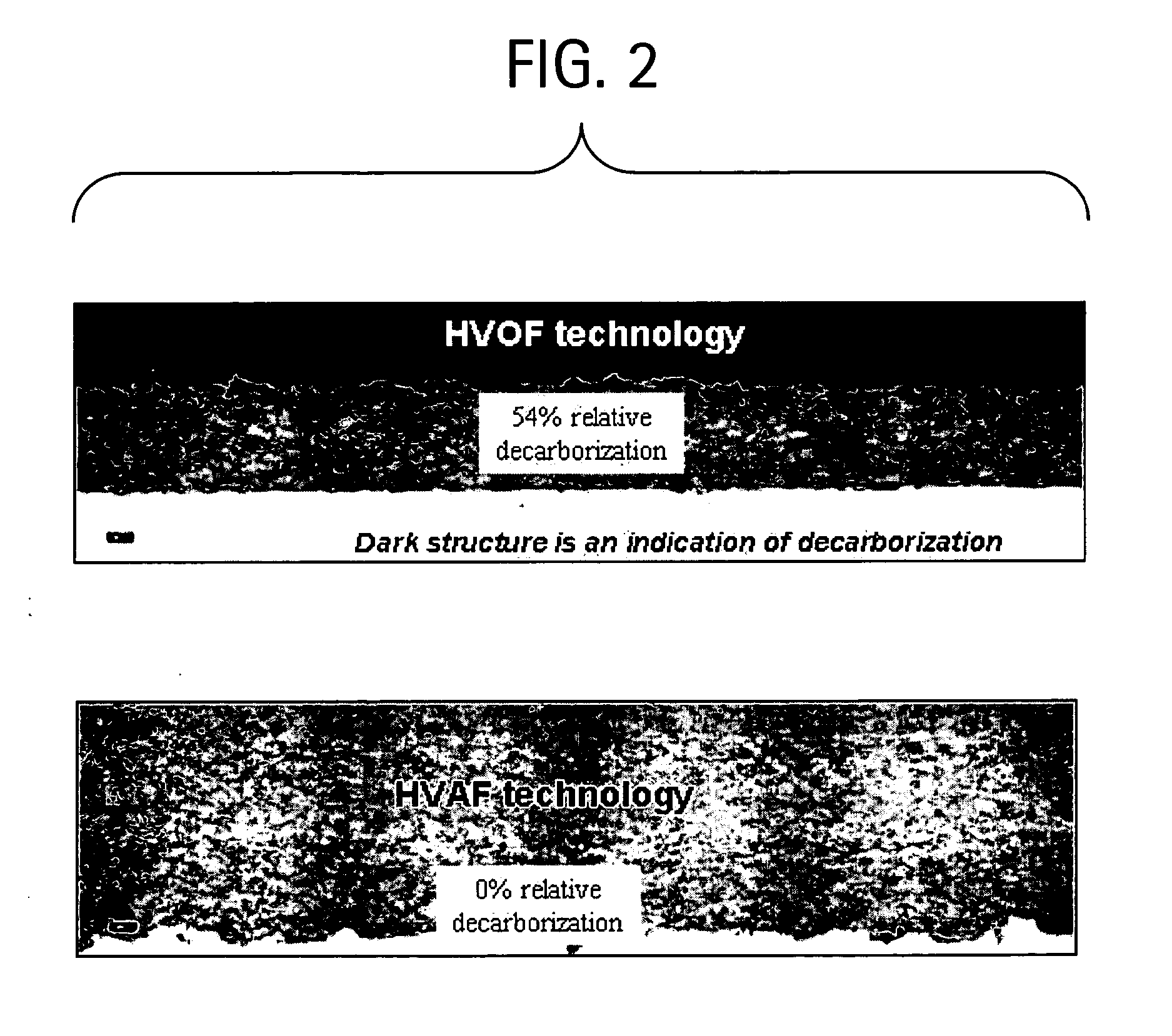
[0020] Disclosed herein are coating compositions and coating methods that provide erosion resistance to components prone to silt erosion while simultaneously maintaining suitable corrosion resistance. In one embodiment, a high velocity air fuel (HVAF) process is employed for depositing erosion resistant coatings onto a component surface. The HVAF process is a material deposition process in which coatings are applied by exposing a substrate to a high-velocity jet at about 600 m / s to about 800 m / s of about 5 to about 45 micron particles that are accelerated and heated by a supersonic jet of low-temperature “air-fuel gas” combustion products. The HVAF spraying process deposits an extremely dense (minimal porosity) and substantially non-oxidized coating. Moreover, increased thicknesses can be obtained relative to other thermal plasma spray processes, resulting in turbine components exhibiting superior erosion resistance properties. The HVAF process utilizes a fuel such as propane or pro...


PUM

PropertyMeasurementUnit
diameteraaaaaaaaaa
diameteraaaaaaaaaa
particle velocityaaaaaaaaaa

Abstract

Erosion resistant coating processes and material improvements for line-of-sight applications. The erosion resistant coating composition includes nanostructured grains of tungsten carbide (WC) and/or submicron sized grains of WC embedded into a cobalt chromium (CoCr) binder matrix. A high velocity air fuel thermal spray process (HVAF) is used to create thick coatings in excess of about 500 microns with high percentages of primary carbide for longer life better erosion resistant coatings. These materials and processes are especially suited for hydroelectric turbine components.

Description

CROSS REFERENCE TO RELATED APPLICATIONS [0001] This application claims the benefits of U.S. Provisional Patent Application Ser. No. 60 / 524,098 filed Nov. 21, 2003, which is fully incorporated herein by reference.BACKGROUND [0002] The present disclosure generally relates to coating methods and compositions for turbine components. These coatings and processes are especially suitable for hydroelectric turbine components, which exhibit improved silt erosion resistance from the coating. [0003] Components are used in a wide variety of industrial applications under a diverse set of operating conditions. In many cases, the components are provided with coatings that impart various characteristics, such as corrosion resistance, heat resistance, oxidation resistance, wear resistance, erosion resistance, and the like. [0004] Erosion-resistant coatings are frequently used on hydroelectric turbine components, and in particular, the runner and the guide vanes, for Francis-type turbines, and the ru...

Claims


Application Information

Patent Timeline
Patent Type & Authority Applications(United States)
IPC IPC(8): C23C4/06C23C24/04C23C26/02C23C30/00
CPCC23C4/06C23C24/04C23C30/00Y10T428/25Y10T428/263Y10T428/252C23C4/124C23C4/129
Inventor GRAY, DENNIS MICHAELANAND, KRISHNAMURTHYNELSON, WARREN ARTHURAUNEMO, HANSDEMERS, ALAINROMMETVEIT, OLAV
Owner GENERAL ELECTRIC CO
Why Eureka
Try Eureka