

Coatings
- Summary
- Abstract
- Description
- Claims
- Application Information
AI Technical Summary
Benefits of technology
Problems solved by technology
Method used
Image

Examples
example 2
Examples of Perfluoro Alkyl Acrylate Co-polymerisation with Crosslinker to Show Improvements in Electrical Resistance
[0132]Perfluorooctyl acrylate monomer was mixed with a single crosslinker from the following list:
[0133]VINYL ESTERS: Divinyl adipate (DVA)
[0134]VINYL ETHERS: 1,4-Butanediol divinyl ether (BDVE); 1,4 Cyclohexanedimethanol divinyl ether (CDDE)
[0135]DI- or TRI-VINYLS: 1,7-Octadiene (1,7-OD); 1,2,4-Trivinylcyclohexane (TVCH);
[0136]DI VINYL with alkyl fluoro group: 1,6-divinylperfluorohexane (DVPFH)
[0137]DI VINYL with silicon group: 1,3-Divinyl tetramethyldisiloxane (DVTMDS)
[0138]DI VINYL with cyclic ring and carboxylate groups: Diallyl 1,4-cyclohexanedicarboxylate (DCHC)
[0139]DI ACRYLATE: 1H1H,6H,6H-perfluorohexanediol diacrylate (PFHDA) The crosslinker was mixed with the PFAC6 as a percentage by volume for the following percentages: 20, 40, 60, 80, and 100%.
[0140]Plasma initiated polymerisation reactions were carried out in a 3 litre glass plasma chamber. The substrates...
example 3
Example of Crosslinker Concentration on Water Repellent Coating
[0141]Water repellent coatings were prepared in a 125 litre volume chamber using PFAC6 with different levels of divinyl adipate (DVA) and using helium as a carrier gas. The deposition process consisted of a 3 minute CW step with 300W power and a pulsed step with 150W power and an RF pulse duty cycle of 0.018%. Silicon wafer was used as the test substrates and the contact angle of the coated wafer was determined by applying a 3 ul drop of deionised wafer onto the coated wafer and measuring the contact angle using a VCA Optima (AST products) with image analysis software. The variation of contact angle with (v / v) % DVA crosslinker is shown in FIG. 4. It was also noted that for the 10 (v / v) % DVA concentration, the water drop left a mark on the coated wafer where it's circumference had been. This indicated that a higher level of crosslinker was required to give a more stable coating. This observation, in combination with the...
example 4
Example of AFM Measurement of Monomer / Crosslinker Co-Polymer Coating
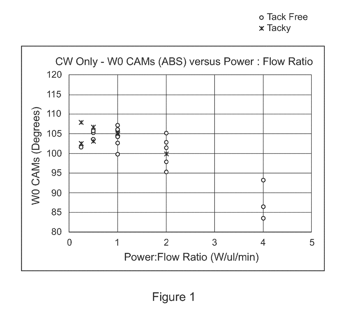
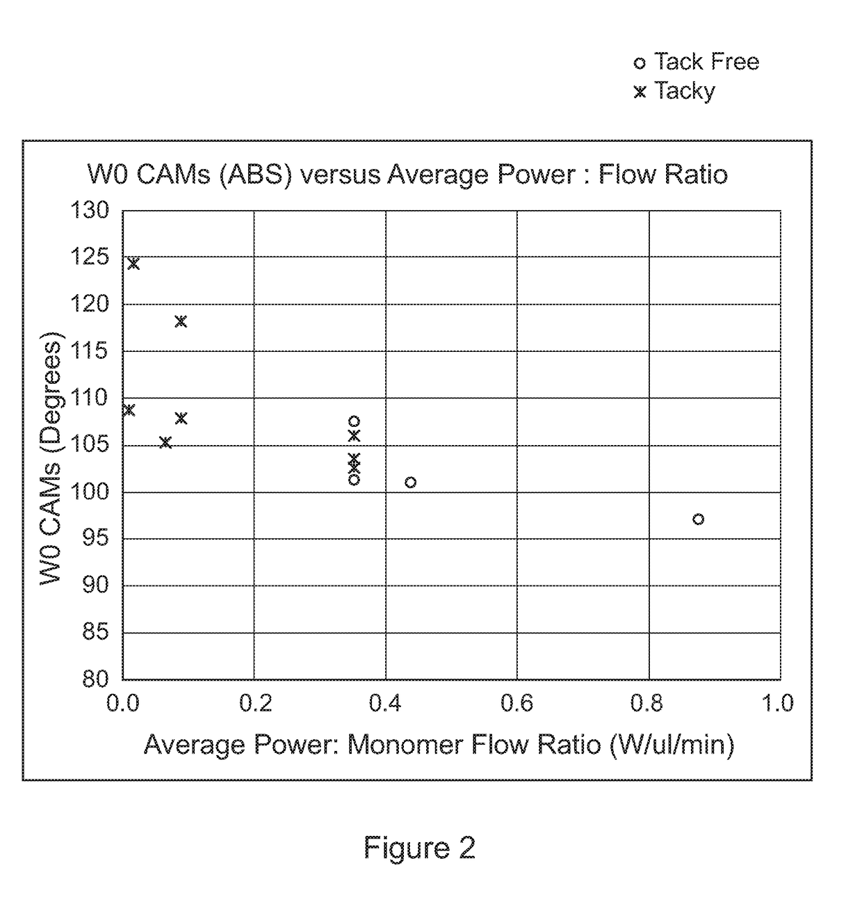
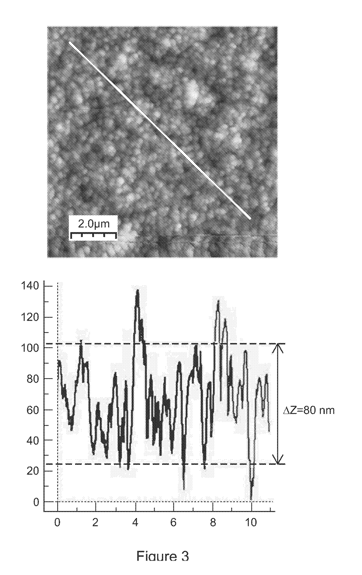
[0143]A barrier-style coating was prepared in a 22 litre volume chamber using PFAC6 with 10% DVA. The deposition process consisted of a 1 minute CW step with a CW power to flow ratio of 3.9 (W / microliter / min), and a pulsed step with a PW power / monomer flow ratio of 0.28 (W / microlitres / min). FIG. 6 shows the representative topographical and phase contrast images were obtained from all the samples. High spatial resolution images show mainly the structures of areas between the raised features. The RMS roughness of the coating is 1.65 nm and the Δz / d=0.05. As the Δz / d value is <0.15, then this indicates that the physical layer is substantially pinhole free.
PUM
| Property | Measurement | Unit |
|---|---|---|
| Temperature | aaaaa | aaaaa |
| Time | aaaaa | aaaaa |
| Power | aaaaa | aaaaa |
Abstract
Description
Claims
Application Information