Plasma spray method and apparatus for applying a coating utilizing particle kinetics

a technology of particle kinetics and spray method, which is applied in the field of plasma spray method and apparatus for applying a coating utilizing particle kinetics, can solve the problems of limited cold gas dynamic spray method and particle siz

Inactive Publication Date: 2005-06-09
FLAME SPRAY IND
View PDF10 Cites 84 Cited by
  • Summary
  • Abstract
  • Description
  • Claims
  • Application Information

AI Technical Summary

Benefits of technology

[0008] The present invention provides a method and apparatus by which particles of metals, alloys, polymers and mechanical mixtures of the forgoing and with ceramics and semiconductors having a broad range of particle sizes, may be applied to substrates using a novel plasma spray coating method which provides for first feeding the cold high pressure carrier gas with entrained powder particle material into the cold high pressure main gas prior to heating the combined gases and powder and then converging the cold combined gas / powder mixture coaxially into a plasma flame thereby controllably heating the gas as well as the powder particles. The plasma flame can heat the combined gas and particles in excess of 2500 degrees Fahrenheit.
[0012] Another object of the invention is to use the cold carrier gas and main gas to cool the nozzle instead of water cooling the nozzle. Typically in a water-cooled non-transferred plasma arc spray system approximately 35% of the energy of the plasma ends up heating the water, which is used to cool the nozzle. By using the cold carrier gas and main gas to cool the nozzle, the plasma is then used to heat the carrier gas and main gas and ends up being a very efficient system.
[0017] A further object of the invention is to provide a method and apparatus for producing high performance well bonded coatings, which are substantially uniform in composition and have very high density with very low oxides content formed within the coating.

Problems solved by technology

The improvement over the prior art lays in the fact that, regarding Alkhimov et al, the cold gas dynamic spray method is limited to the use only a particle size range of 1-50 micron.
This limitation has been found by Van Steenkiste et al to be due to the heated main high pressure gas being cooled by injecting into it the cold high pressure carrier gas / powder.
However, the kinetic spray coating method and apparatus of Van Steenkiste et al state an upper limit of the particle size range 106 microns, based on experimental results.

Method used


Image

  • Plasma spray method and apparatus for applying a coating utilizing particle kinetics
  • Plasma spray method and apparatus for applying a coating utilizing particle kinetics
  • Plasma spray method and apparatus for applying a coating utilizing particle kinetics

Examples


Embodiment Construction

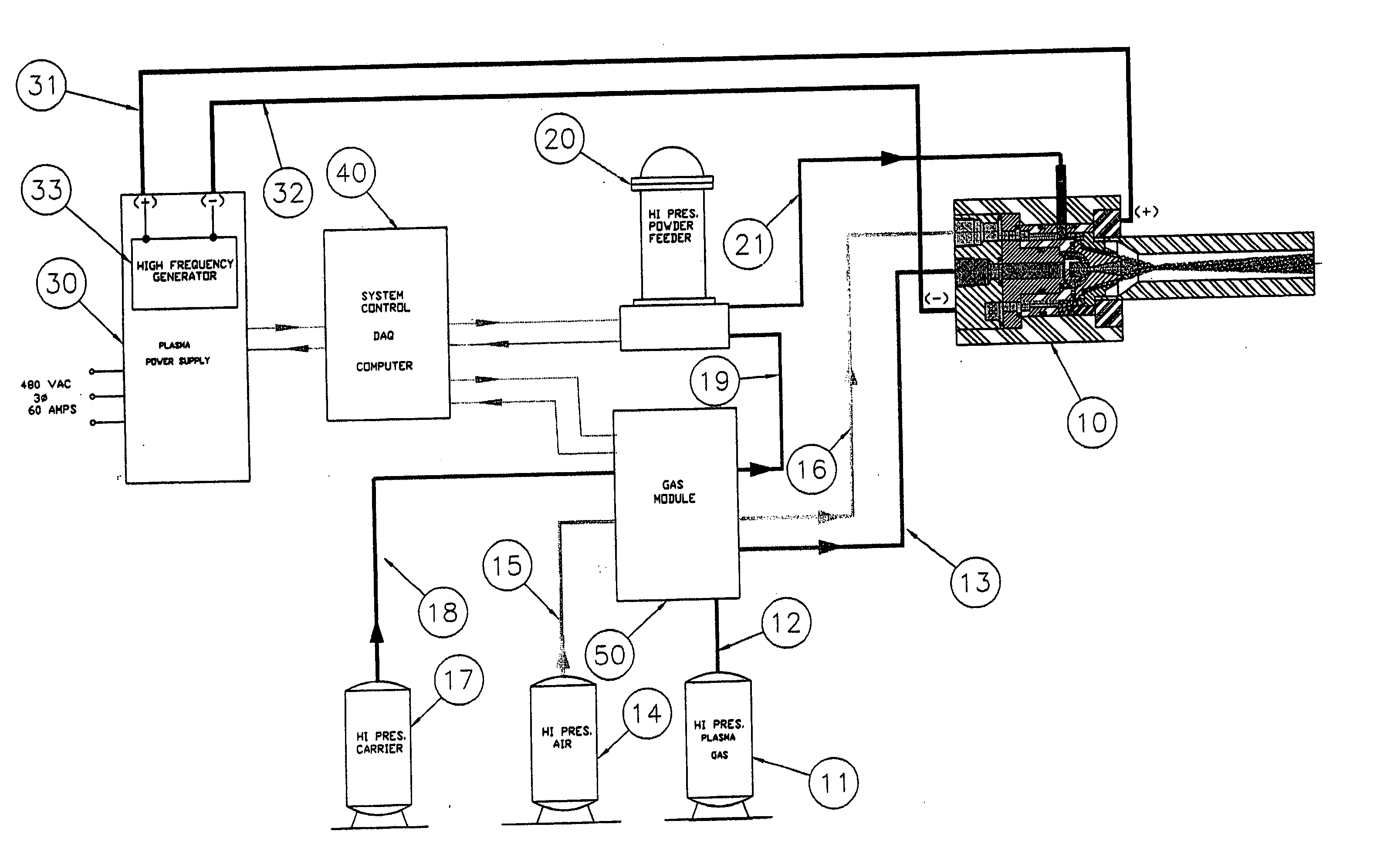
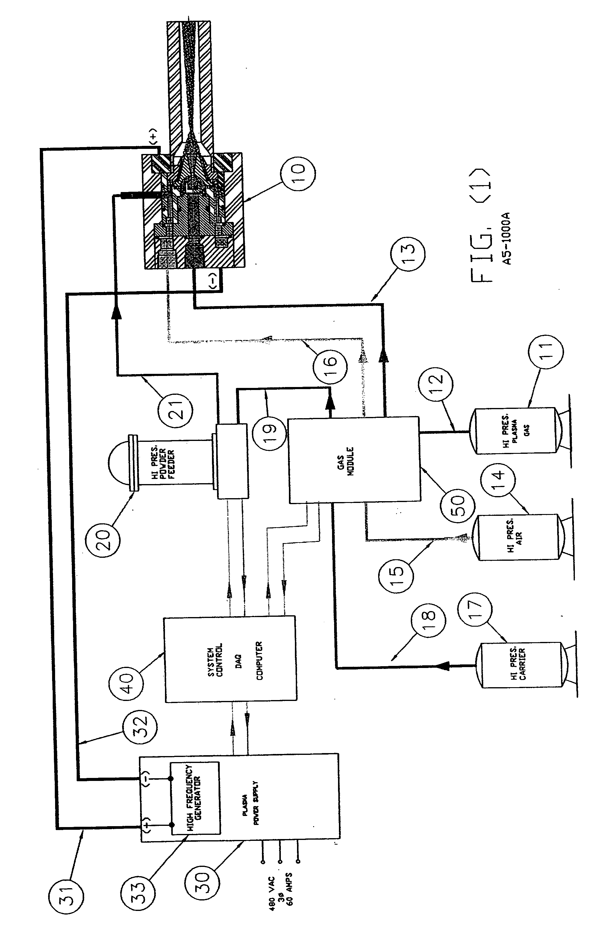
[0027] Reference is first made to FIG. 1 in which a high-velocity plasma spray apparatus constructed in accordance with the invention includes a high pressure plasma spray (HPPS) assembly 10, a high pressure powder feeder assembly 20, a plasma power supply 30, a system control console 40 and a gas module 50. A high pressure plasma gas 11 which typically could be argon, nitrogen or a mixture of argon / hydrogen and having a pressure of between 200 psig and 600 psig, is fed to the gas module 50 through hose 12 and them fed from the gas module 50 through hose 13 to the HPPS torch assembly 10. Electrical power is supplied to the HPPS 10 from the plasma power supply 30 by means of cables 31 and 32. High-pressure compressed gas 14, which can be air, nitrogen, helium or any mixture of these gases and having a pressure of between 200 psig and 600 psig, is supplied to the gas module 50 by means of hose 15 and then fed to the HPPS torch assembly through hose 16. The high pressure carrier gas 17...


PUM

PropertyMeasurementUnit
pressureaaaaaaaaaa
pressureaaaaaaaaaa
particle sizeaaaaaaaaaa

Abstract

A method of operation of a plasma torch and the plasma apparatus to produce a hot gas jet stream directed towards a workpiece to be coated by first injecting a cold high pressure carrier gas containing a powder material into a cold main high pressure gas flow and then directing this combined high pressure gas flow coaxially around a plasma exiting from an operating plasma generator and converging directly into the hot plasma effluent, thereby mixing with the hot plasma effluent to form a gas stream with a net temperature based on the enthalpy of the plasma stream and the temperature and volume of the cold high pressure converging gas, establishing a net temperature of the gas stream at a temperature such that the powdered material will not melt or soften, and projecting the powder particles at high velocity onto a workpiece surface. The improvement resides in mixing a cold high pressure carrier gas with powder material entrained in it, with a cold high pressure gas flow of gas prior to mixing this combined gas flow with the plasma effluent which is utilized to heat the combined gas flow to an elevated temperature limited to not exceeding the softening point or melting point of the powder material. The resulting hot high pressure gas flow is directed through a supersonic nozzle to accelerate this heated gas flow to supersonic velocities, thereby providing sufficient velocity to the particles striking the workpiece to achieve a kinetic energy transformation into elastic deformation of the particles as they impact the onto the workpiece surface and forming a dense, tightly adhering cohesive coating. Preferably the powder material is of metals, alloys, polymers and mixtures thereof or with semiconductors or ceramics and the powder material is preferably of a particle size range exceeding 50 microns.

Description

CROSS REFERENCE TO RELATED APPLICATIONS [0001] This invention claims priority to Provisional Application Ser. No. 60 / 346,540 filed Jan. 8, 2002 titled “PLASMA SPRAY METHOD AND APPARATUS FOR APPLYING A COATING UTILIZING PARTICLE KINETICS”, by Keith Kowalsky and Daniel Marantz.FIELD OF INVENTION [0002] The present invention is directed to a method and device for low temperature, high velocity particle deposition onto a workpiece surface from an internal plasma generator, and more particularly to a thermal spray method and device in which the in-transit temperature of the powder particles is below their melting point and wherein a cohesive coating is formed by conversion of kinetic energy of the high velocity particles to elastic deformation of the particles upon impact against the workpiece surface. BACKGROUND OF THE INVENTION [0003] Until Recently, in thermal spraying, it has been the practice to use the highest temperature heat sources to spray metal and refractory powders to form a...

Claims


Application Information

Patent Timeline
Patent Type & Authority Applications(United States)
IPC IPC(8): C23C4/12
CPCC23C24/04C23C4/127C23C4/134
Inventor KOWALSKY, KEITH A.MARANTZ, DANIEL R.
Owner FLAME SPRAY IND
Why Eureka
Try Eureka