Radiation-image conversion panel and process of producing the same

a radiation-image conversion and radiation-image technology, applied in the direction of optical radiation measurement, fluorescence/phosphorescence, instruments, etc., can solve the problems of deteriorating image quality, interference fringes or imperfections in the radiographic image, distortion or wrinkles in the protective layer, etc., to achieve satisfactory image quality, high degree of sensitiveness, and practical life

Inactive Publication Date: 2005-06-30
FUJIFILM HLDG CORP +1
View PDF6 Cites 25 Cited by
  • Summary
  • Abstract
  • Description
  • Claims
  • Application Information

AI Technical Summary

Benefits of technology

[0011] An object of the present invention is to provide a radiation-image conversion panel which is so moistur

Problems solved by technology

However, when the thickness of the protective layer is small, unevenness (such as interference fringes) or imperfection is likely to occur in the radiographic image.
However, when an inorganic layer is formed on a support (e.g., a PET film) for the protective layer or an organic layer by vacuum deposition, distortion or wrinkles are likely to occur in the protective layer, and therefore the quality of the images obtained by use of the radiation-image conversion panel deteriorates.
However, when the thickness of the support or the organic layers is increas

Method used


Image

  • Radiation-image conversion panel and process of producing the same
  • Radiation-image conversion panel and process of producing the same
  • Radiation-image conversion panel and process of producing the same

Examples


first embodiment

EXAMPLES OF THE PRESENT INVENTION

example 1

[0086] (1) Formation of Fluorescent Layer

[0087] As the evaporation sources, a powder of cesium bromide (CsBr) with the purity of 4N or higher and a powder of europium bromide (EuBr2) with the purity of 3N or higher are prepared, and minor elements in each of the above powders are analyzed by the inductively coupled plasma mass spectrometry (ICP-MS). The result of the analysis shows that in CsBr, the content of each of alkali metal elements (Li, Na, K, and Rb) other than Cs is 10 ppm or less, and the content of each of the other elements including alkaline-earth metal elements (Mg, Ca, Sr, and Ba) is 2 ppm or less. In addition, in EuBr2, the content of each of the rare-earth elements other than Eu is 20 ppm, and the content of each of the other elements is 10 ppm or less. Since the above powders are highly hygroscopic, these powders are stored in a desiccator in which a dry atmosphere having a dew point of −20° C. or lower is maintained, and each powder is taken out immediately befo...

example 2

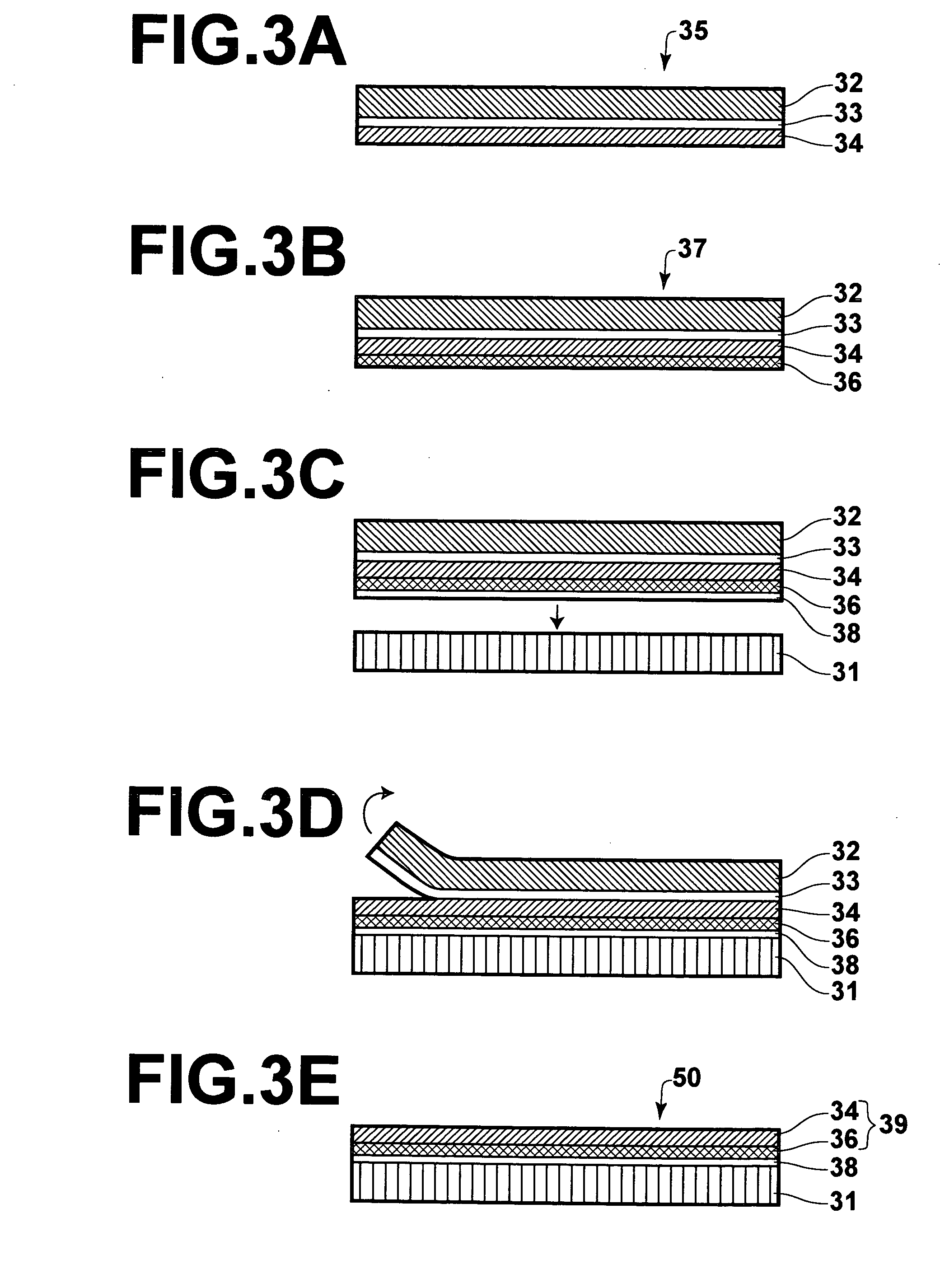
[0092] The radiation-image conversion panel as the example 2 is different from the radiation-image conversion panel as the example 1 only in the manner of fixing the protective sheet to the stimulable-phosphor layer. That is, in the process of forming the protective layer in the example 2, the protective sheet is fixed to the upper surface and side surfaces of the stimulable-phosphor layer by vacuum sealing (i.e., forming an opening at an end of the protective sheet for evacuation, attaching the protective sheet to the stimulable-phosphor layer, performing evacuation through the opening, and closing the opening with a stopper so as to seal the stimulable-phosphor layer in the protective sheet.


PUM


Abstract

In a radiation-image conversion panel, a fluorescent layer containing a stimulable phosphor and a protective layer are formed on a support in this order. The protective layer has a water-vapor transmission rate of 1 g/m2/24h or lower at 40° C. and a reflectance of 3% or lower at a wavelength of light emitted from the stimulable phosphor. In addition, the protective layer may be obtained by attaching a removable film to a thin transparent film so as to produce a laminated film, forming a vapor-barrier layer on an exposed surface of the thin transparent film by vacuum deposition so as to produce a moisture-resistant film, placing the moisture-resistant film on the fluorescent layer, and removing the removable film from the moisture-resistant film.

Description

BACKGROUND OF THE INVENTION [0001] 1. Field of the Invention [0002] The present invention relates to a radiation-image conversion panel for use in the radiation-image conversion techniques utilizing stimulable phosphors, and a process for producing such a radiation-image conversion panel. [0003] 2. Description of the Related Art [0004] The computed radiography (CR) is known as a technique for recording and reproducing a radiographic image. In the computed radiography (CR), a system constituted by a radiographic-image record device, a radiographic-image reading device, and the like is used, and the stimulable (photostimulable) phosphor is used in the system. When the stimulable phosphor is irradiated with radiation such as X-rays, a portion of the energy of the radiation is accumulated in the stimulable phosphor. Thereafter, when the stimulable phosphor is irradiated with excitation light such as visible light, the stimulable phosphor emits stimulated luminescence the amount of which...

Claims


Application Information

Patent Timeline
IPC IPC(8): G03B42/08
CPCG03B42/08
Inventor KUBOTA, HAJIMETAKASU, ATSUNORIKIDO, TAKEO
Owner FUJIFILM HLDG CORP
Why Eureka
Try Eureka