Projection optical system

a technology of which is applied in the field of projection exposure apparatus, can solve the problems limited number of suitable materials for lenses in projection optical system and illumination optical system having a large enough transmittance at short wavelengths, and inability to achieve the effect of reducing the problem of deterioration of optical performan

Inactive Publication Date: 2005-06-30
CARL ZEISS SMT GMBH
View PDF17 Cites 0 Cited by
  • Summary
  • Abstract
  • Description
  • Claims
  • Application Information

AI Technical Summary

Benefits of technology

[0015] In view of this and other needs, the present invention aims at reducing the problem of deterioration

Problems solved by technology

However, the transition to ever shorter wavelengths is associated with a number of problems.
In particular, the number of suitable materials for lenses in the projection optical system as well as in the illumination optical system having a large enough transmittance at short wavelengths is very limited.
Furthermore, the materials that are satisfactory in terms of transmittance often suffer damage upon exposure to radiation.
The change in density of an exposed area in a lens in a pr

Method used


Image

  • Projection optical system
  • Projection optical system
  • Projection optical system

Examples


Embodiment Construction

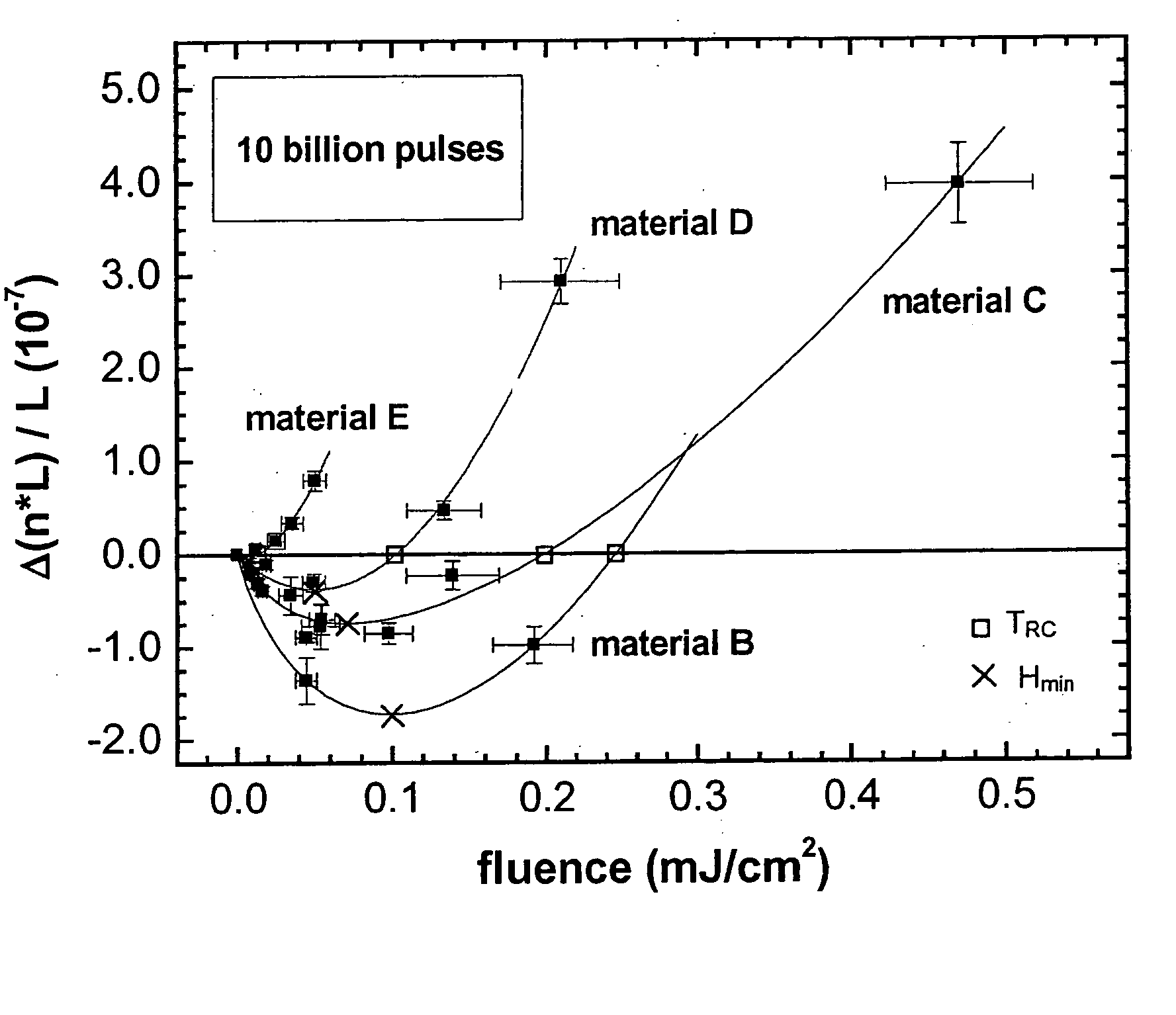
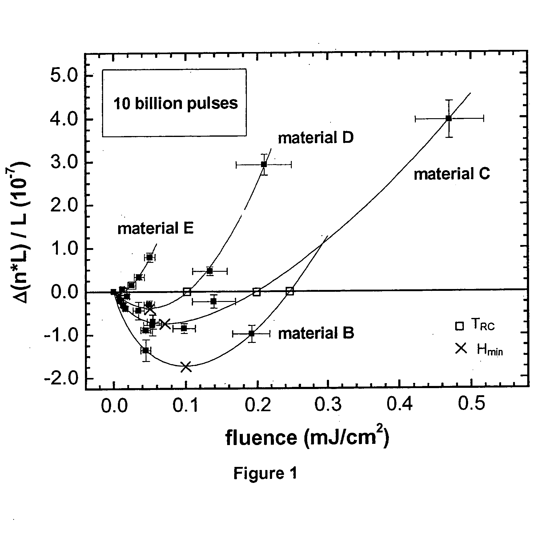
[0121]FIG. 1 illustrates results from experiments in which 10 cm long samples of lens materials B to E were each exposed to 10 billion pulses of radiation having fluence values in the range of 0.01 to 0.5 mJ / cm2. The relative optical path length difference Δ(n·L) / L of the respective sample is plotted against the fluence value that the respective sample of the lens material was exposed to. The light source used was an ArF excimer laser emitting light of 193 nm wavelength (λ). The pulse length (more precisely: integral square pulse width) was about 25 ns. The relative optical path length difference Δ(n·L) / L was measured using an interferometric method (using light of 633 nm wavelength).

[0122] As can be clearly seen in FIG. 1, each lens material shows a characteristic dependency of the change in physical properties on the exposure fluence value.

[0123] Each lens material can be characterised by a characteristic transition point (TRC) which marks the fluence value upon radiation to whi...


PUM

PropertyMeasurementUnit
Fractionaaaaaaaaaa
Fractionaaaaaaaaaa
Fractionaaaaaaaaaa

Abstract

Radiation-induced damage to a lens material in a projection exposure system is reduced by selection of maximum design fluence values HD for lenses and at least one lens made of a material having a characteristic transition point TRC after exposure to a given amount of radiation, wherein, for instance, TRC<0.8. HD among other relationships and/or characteristics of the lenses.

Description

BACKGROUND OF THE INVENTION [0001] 1. Field of Industrial Applicability [0002] The present invention generally relates to a projection exposure apparatus for photolithography, and, more particularly, to a projection exposure apparatus adapted to reduce a decrease in performance due to radiation-induced damage of lens material(s) comprised therein. [0003] 2. Prior Art [0004] Lithographic processes are commonly used in the manufacture of semiconductor elements, such as integrated circuits (ICs), LSIs, liquid crystal elements, micropatterened members such as thin-film magnetic heads and micromechanical components. A projection exposure apparatus used for lithography generally comprises an illumination optical system with a light source and a projection optical system. Light from the illumination optical system illuminates a patterning structure (mask) with a given pattern and the projection optical system transfers an image of the patterning structure pattern onto a photo-sensitive sub...

Claims


Application Information

Patent Timeline
IPC IPC(8): G03F7/20
CPCG03F7/70983G03F7/70958
Inventor KRAHMER, DANIELEVA, ERIC
Owner CARL ZEISS SMT GMBH
Why Eureka
Try Eureka